
Description
This article will guide you through how to start an engraving task with the Auto Feeder.
Unboxing:
| Auto Feeder Package | |||
| # | Item Name | Description | Q'ty |
| 1 | Feeder | The main part that controls the material's movement and engraving path. | 1pc |
| 2 | Rail | The part has built-in white ball wheels, allowing the material to move smoothly. | 5pcs |
| 3 | Rail fixing beam | It's the bars or beams that are to be installed horizontally to steady the structure. | 1pc |
| 4 | Belt | It's the timing belt that will be mounted on the feeder, responsible for its movement. | 1pc |
| 5 | Belt clamp | It is the belt's retainer used to fix the belt's position. | 2pcs |
| 6 | Rail connector | It is used to connect the rails to have longer rails. | 6pcs |
| 7 | Edge guide rollers | They are used to limit the material's position from going off in the wrong direction. | 1set |
| 8 | Edge guide roller platform | It's the platfrom where the rollers will be sitting on it. The positon of the platforms can be changed depending on the size of the material. | 2pcs |
| 9 | Rail riser | It can be considered as foot used to raise the setup. | 5pcs |
| 10 | Adapter | It's the cable's adapter which one slot is for the machine's cable and the other is for the feeder's cable. | 1pc |
| 11 | Rail magnet | The purpose of the part is to limit the material's positon similar to the rollers. It is also used to stick the setup to the machine. | 4pcs |
| 12 | L-Shaped Positioning Bracket | The magnet will be installed on the bracket to stick to the machine. | 2pcs |
| 13 | M5 T-Nut | It will be the nut for the magnet. | 4pcs |
| 14 | Rail clamp | This will be used to fix the setup on the machine. Some of the setup won't need this part. | 1pc |
| 15 | Cable | The cable to connet to the machine and the adapter. | 1pc |
| 16 | M5*6 screw | Short screw | 6pcs |
| 17 | M5*12 screw | Midium screw | 6pcs |
| 18 | M5*22 screw | Long screw | 6pcs |
| 19 | M4 Hex screw driver | This tool is used to install the setup. | 1pc |
| 20 | 2.5mm Hex wrench | This tool is used to install the setup. | 1pc |
| 21 | 2mm Hex wrench | This tool is used to install the setup. | 1pc |
| 22 | 10mm Open-end wrench | This tool is used to adjust or replace the feeder's wheel. | 1pc |
| 23 | White Ball Wheel | This is the spare for the white ball wheels that are built-in on the rails. | 3pcs |
| Extension Package | |||
| # | Item Name | Description | Q'ty |
| 1 | Rail | The part has built-in white ball wheels, allowing the material to move smoothly. | 6pcs |
| 2 | Rail connector | It is used to connect the rails to have longer rails. | 6pcs |
| 3 | Rail fixing beam | It's the bars or beams that are to be installed horizontally to steady the structure. | 2pcs |
| 4 | Rail riser | It can be considered as foot used to raise the setup. | 5pcs |
| 5 | M5*6 screw | Short screw | 8pcs |
| 6 | M5*22 screw | Long screw | 6pcs |
| 7 | M5*25 screw | Ultral long screw | 4pcs |
| 8 | 3m (300mm) belt | This belt will be used to replace the original one when using the longest setup. | 1pc |
| 9 | Extension Cable | This cable will be used to extened the cable of the feeder when using the longest setup. | 1pc |
| 10 | White Ball Wheel | This is the spare for the white ball wheels that are built-in on the rails. | 3pcs |
Step 1
Remove the metal base of Ador.
Unscrew these two screws to remove the metal base.
Remove the metal base by lifting the machine a little and taking out the base directly.
Step 2
Turn off the machine and remove the power cord.
Step 3
Find the main rail (the one with a belt) and remove the rail connectors.
(Other rail connectors may be in other rails.)
Step 4
Release the belt and find its long side.
Loosen the belt retainer by using the small Allen key.
| Short Side of Belt | Long Side of Belt |
Meanwhile, please tighten the belt retainer on the short side.
Step 5
Prepare the feeder and the main rail.
Insert the main rail into the pulley with the long side of the belt going in first.
Hook the belt upward onto the gear and guide it downward, forming a peak shape.
It is essential to insert it in this direction, ensuring that the long side of the belt remains on the same side as the feeder's flat surface.
Step 6
Prepare two rail connectors and an extension rail (with white ball wheels).
Each block has four screws. Secure two screws on the main rail and two on the extension rail to achieve a firm clamping effect.
(Note: Ensure the extension rail has white wheels, as the wheels are for the feeders to move. The connectors have to be on the same side of the white wheels and at the bottom of the white wheels.)
Step 7
Fix the belt at the long side with the belt retainer that was removed earlier.
(Please ensure the belt is tight before fixing it.)
Please ensure the belt is well hooked on the pulley. If not, please remove the belt retainer and re-insert the feeder.
Step 8
Prepare two rail connectors and an extension rail (with white ball wheels).
Connect the rail fixing beam to the feeder rail and install it using the screw hole in the center of the beam.
Step 9
Prepare one rail and one M5x22 screw.
Attach the rail to the beam near the center screw hole.
Step 10
Prepare 2 rail risers and 2 medium screws (M5x12).
Install the rail risers on both sides of the rail fixing beam, with the hand-tightened screw facing the feeder side.
Step 11
Prepare two rails.
Install the two rails on top of the support legs on both sides, with the white rollers facing downward. Secure them using the hand-tightened screws.
Step 12
Prepare 2 Rail risers.
Install the rail risers under the edges of the rails on both sides and secure them using hand-tightened screws.
Step 13
Prepare 1 rail riser and 1 M5\*12 screw.
Then, install the rail riser at the back of the rail.
Step 14
Prepare 2 rail magnets and M5\*22 screws.
Install the rail magnets on the top edge of the two rail sides, ensuring the silver magnetic side is facing the feeder.
Step 15
Prepare 2 rail magnets, 2 medium screws (M5x12), and 2 T-nuts.
Combine the nuts and screws, but do not tighten them fully; just ensure that the screws are engaged.
Then, install the magnet blocks on top of the rail fixing beam, securing them temporarily. Their position will be adjusted in subsequent steps.
If the entire structure is not level or the tabletop surface is not flat, you can adjust the height of the support risers.
Step 16
Prepare two Edge guide roller platforms.
Then install them on the center Rail fixing beam, facing backward, towards the Feeder side.
|
|
The platforms can be moved, and they may be moved depending on your material's width, which will be covered later in this article.
Step 16
Take out the connection cable.
Flip the machine over to locate the socket, then insert the connector.
Step 17
Place the machine onto the feeder, as shown in the image below.
Make sure the machine does not press down on the connector cable.
Make sure the magnet is securely attached to the machine casing.
Step 18
Find the adapter, insert the other end of the connection cable into the box, and then attach the adapter to the machine.
Step 19
If there is a cable tie on the Feeder's connection cable, please cut it.
Connect the Feeder's cable to the adapter.
Step 20
Place the material, ensure it is level against the Feeder, and then tighten the thumbscrews to secure the material.
Note: When the bottom cover is open, the autofocus probe may not be able to reach the surface of the material. In this case, you'll need to raise the material by approximately 10–12 mm. If the material itself is already over 12 mm thick, additional elevation is not necessary.
In the example shown in the video below, the material is raised by 10 mm using two 5 mm wooden boards, with the third layer being the actual material to be engraved.
Push and pull the material forward and backward to test, while observing the material's appearance under the machine's bottom cover to confirm if it is level.
Step 21
Adjust the position of the limit Rail magnets installed in step 14.
Adjust the Edge guide roller platform position according to the video below, aligning it flush with the outer edge of the limit Rail magnet.
Install the rollers. The spring-loaded rollers can be installed on either the left or right without restriction. Their main purpose is to prevent material deviation.
| Reverse Installation (for material thickness less than 5mm) | |
| Forward Installation(for material thickness greater than 5mm) | |
Step 22
Power up the machine.
Ensure the safety lock is inserted at the back of the machine.
Step 23
Ensure you are using the following software and firmware versions.
|
Beam Studio Version 2.5.3 or higher (Tutorial) |
Firmware Version 5.3.8 or higher. (Tutorial) |
|
|
Step 24
Perform focusing by using the screen's AF button or the left side's physical button.
| Press and hold the AF button on the machine panel. | Double-click the focus button on the left side of the machine. |
|
|
|
Step 25
Move the laser head to the area you want to engrave or cut, and then close the lid.
Step 26
- Launch Beam Studio and open the Document Settings.
- Set the Start Position to the Current Position and make it top-left.
-
Enable the Auto Feeder function and input the length of your material (approximately).
Step 27
Import or create a file.
Set the correct parameters based on your material.
Step 28
Using "Framing" to preview the engraving path.
For the "Low Laser", it is a function to output a low laser based on the % you set.
Setting it to 0% is suggested. Otherwise, the engraving path may be marked on the material.
Step 29
Start the task.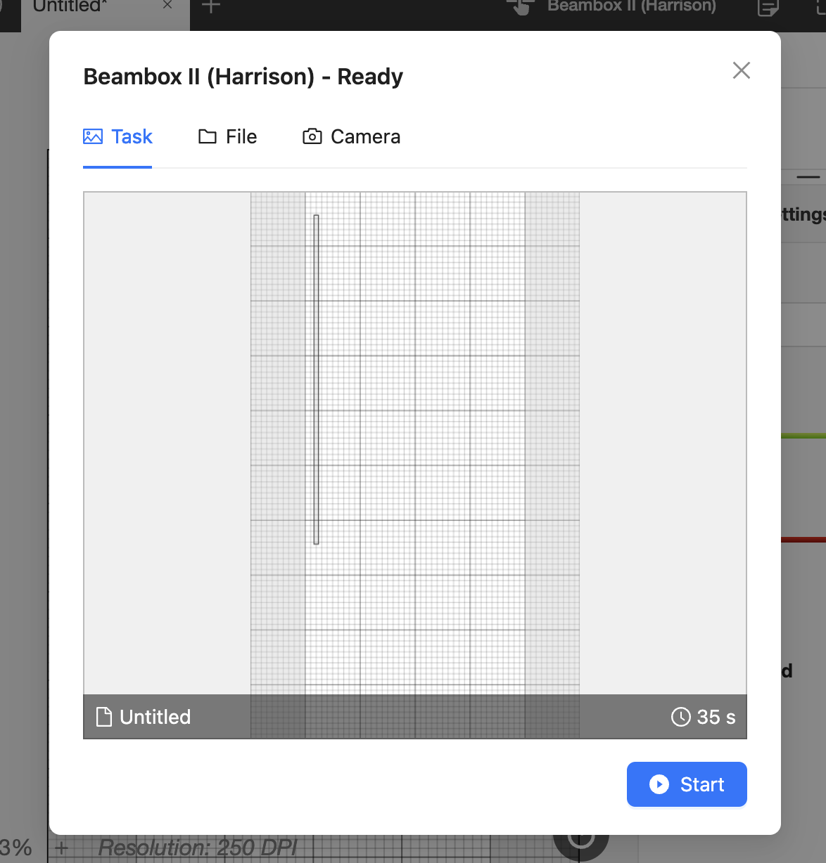
Step 30
Check the result.
If the size of the result differs from your design, use the "Scale" function in Document Settings in Beam Studio and try again.
This function can be used to enlarge or reduce the size of the design in ratio.
- For example, if the rectangle is set to 50cm but the result is 25cm, set the "Scale" to 2, so the result will be enlarged by a factor of 2. (25cm x 2 = 50cm >> Result)
- Another example is if the rectangle is set to 50cm, but the result is 100cm, set the "Scale" to 0.5, so the result will be reduced by a factor of 0.5. (100cm x 0.5 = 50cm >> Result)
#END
Comments
0 comments
Please sign in to leave a comment.