The optical path should be checked every month and realigned if necessary.
Signs of the misaligned optical path:
- Not able to cut through the materials using the default power rate & speed in Beam Studio.
- Having bad engraving results that the engraving patterns in a certain area will be lighter or deeper than other areas, or it getting lighter or deeper in a certain direction.
- The cut section on the material is not vertical after cutting.
Please follow the steps below to check your optical path and realign it if necessary.
(Most of the photos in this content are HEXA's, but the concept, logic, and method on how to align the optical path are the same for Beambox.)
Step 1 - Tool Preparation:
Included in the accessory box:
1|2.5mm hexagonal wrench
2|Phillips screwdriver
3|Double-head wrench
4|Double-sided tape
Prepare by yourself:
1|Cotton swabs
2|Sanitizer spray / Alcohol spray
3|Pliers
Step 2 - Learn How to Make a Pulse:
A. Turn on the machine.
B. Close the lid.
C. Enter Maintain mode and wait til the homing process is done.
D. Find the Pulse button.
E. One press = one pulse, two presses = two pulses, and so on.
#Please always make pulses when the door lid is closed.
Step 3 - Open the Back Cover of Beambox:
Use the Phillips screwdriver to unscrew the screw above the fan at the back of the machine, and the back cover can be opened afterward.
Step 4 - Learn the Locations
Please get familiar with the locations:
- First reflective mirror
- Second reflective mirror
- Third reflective mirror
- 7 locations of the bed that the laser head will be moved to during the checking.
Step 5 - Clean all the mirrors and focus lenses:
Please follow the instructions in the link below to clean all the mirrors and lenses.
5-4 Mirrors and Lens Cleaning
Step 6 - Check the laser dot on the 1st mirror:
This step is to check if the laser tube and the machine are in good condition.
Step overview:
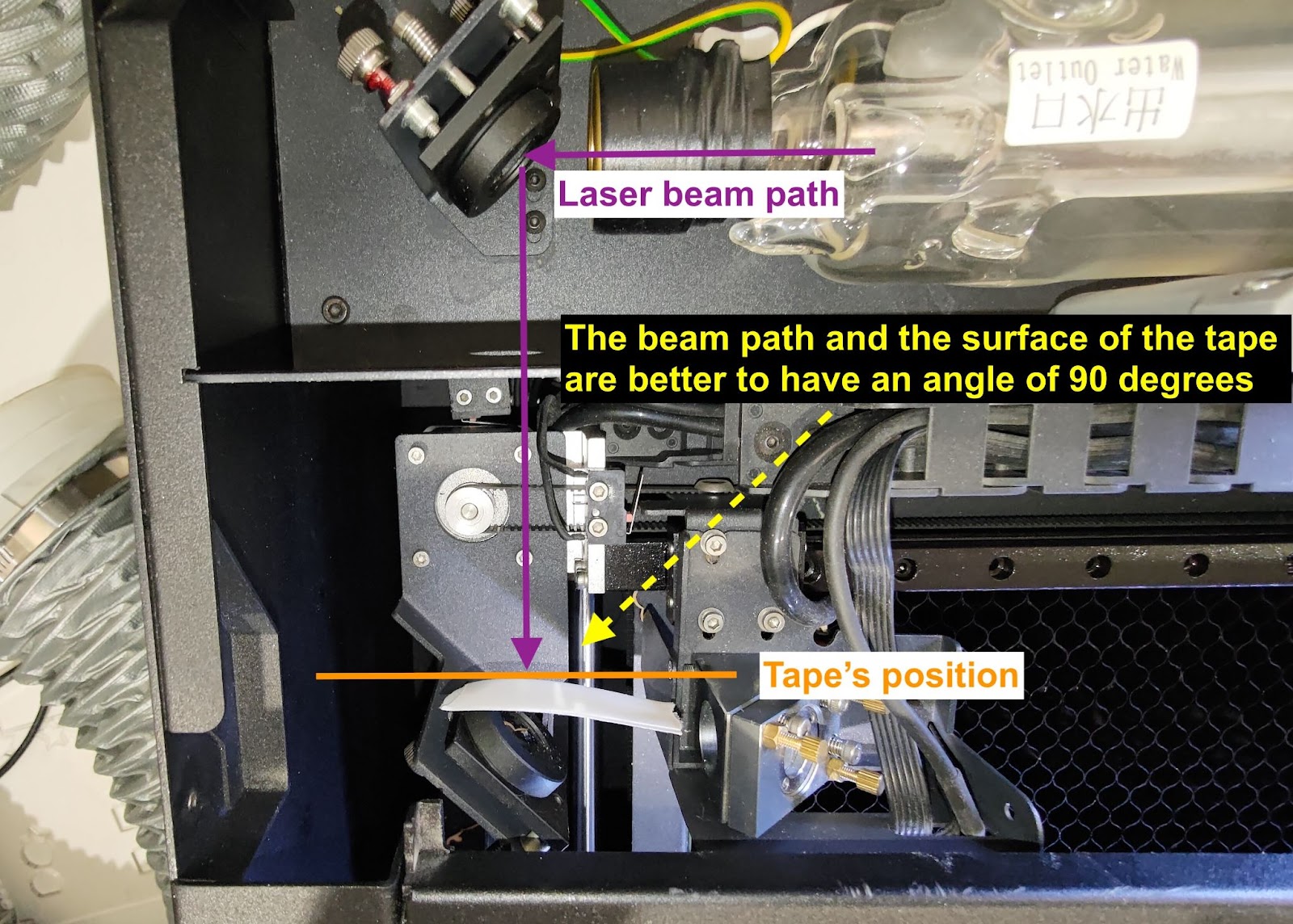
Step 6-1 - Putting Tape and Make Pulses:
Put a two-layer double-sided tape on the 1st mirror, close the back cover, and make five pulses.
Step 6-2 - Check the shape of the dot on the tape:
The shape is good to be as round as possible, and the first piece of double-sided tape in front should be burnt, though.
Good example:
Bad example:

Step 6-3 - Collect the 1st Mirror Tape:
Put the 1st mirror tape on a piece of paper. Write down the position and the number of pulses as in the photo below.

Step 6-4 - Troubleshooting & Reporting:
If your dot is not round, not strong, or similar to the bad examples above, raise the power rate to x2.0 and see if it improves:
-
If the dot becomes stronger, it indicates the laser tube might have declined, you can still finish the OPA process with an increased power rate, or you can contact your local reseller stating that the tube might have declined.
-
If the dot doesn't become stronger or it still has a strange shape, contact your local reseller for further assistance.
(Please share the photo of your pulse result on the 1st mirror with your reseller.)
Step 7 - Check the Path From the 1st to the 2nd mirror:
This step is to check if the path is aligned from the 1st mirror to the 2nd mirror.
Step overview:
Step 7-1 - Create the First Dot for the Top-left Position:
Place a two-layer tape on the 2nd mirror and move the head to the top left corner.
Make three pulses to create the first dot.
Step 7-2 - Create the Second Dot for Bottom-left Position:
Keep the same tape on the 2nd mirror and move the head to the bottom left corner.
Make three pulses to create the second dot.

If there is no dot at the bottom-left position, it indicates that the path is misaligned dramatically.
Please move the head to the middle-left position and try creating a dot at the middle left.
Step 7-3 - Check to see if the first and the second dots overlap
If your dots overlap perfectly, as in the good example photo, it indicates the path is aligned properly.
You can move to Step 7-5.
If they don't overlap, as in the bad examples below, it indicates that from the 1st mirror to the 2nd mirror, the optical path is misaligned, and the 1st mirror has to be adjusted.
Good example:
Bad example:


Step 7-4 - Align the Path from the 1st mirror to the 2nd mirror:
This step will teach you how to align the path from the 1st mirror to the 2nd mirror by adjusting the screws on the 1st mirror.
There are three screws on the 1st mirror, and rotating them clockwise or counter-clockwise will change the beam path meaning the second dot's position will change.
Please note that every time you adjust the screw, the path may change. To ensure accuracy, it's recommended to remove the old tape with the previous dots and use a new two-layer tape to confirm whether the new dots overlap.
Step 7-4-1 - Target the Screw That Will be Adjusted:
Determine the position of your second dot and target the screw and its direction of rotation.
Please see the photo below and find the number that is similar to your second dot's position:
Before you adjust the screw, please learn how to properly loosen the nut:
- First, spray the alcohol on the nuts to melt the gel or glue and wait for a few seconds.
- Next, use the pliers to hold the screw, then loosen the nut with the double-head wrench by turning it counter-clockwise.
For #1:
The second dot needs to go down to the right in order to overlap the first dot
The top-left screw will need to be rotated clockwise. Please refer to the photo below.
For #2:
The second dot needs to go straight down in order to overlap the first dot.
The bottom-left screw will need to be rotated counter-clockwise. Please refer to the photo below.
For #3:
The second dot needs to go down first and then go left in order to overlap the first dot.
The bottom-left screw will need to be rotated counter-clockwise to make the dot go down.
The top-right screw will need to be rotated clockwise to make the dot go left.
Please refer to the photo below.
For #4:
The second dot needs to go right in order to overlap the first dot.
The top-right screw will need to be rotated counter-clockwise. Please refer to the photo below.
For #5:
The second dot needs to go left in order to overlap the first dot.
The top-right screw will need to be rotated clockwise. Please refer to the photo below.
For #6:
The second dot needs to go right first and then go up in order to overlap the first dot.
The top-right screw will need to be rotated counter-clockwise to make the dot go right.
The bottom-left screw will need to be rotated clockwise to make the dot go up.
Please refer to the photo below.
For #7:
The second dot needs to go straight up in order to overlap the first dot.
The bottom-left screw will need to be rotated clockwise. Please refer to the photo below.
For #8:
The second dot needs to go up to the left in order to overlap the first dot
The top-left screw will need to be rotated counter-clockwise. Please refer to the photo below.
Step 7-4-2 - Tighten the Nut After adjusting:
Please tighten the nut after adjusting the screw by turning it clockwise.
Step 7-5 - Collect the 2nd Mirror Tape:
Put the 2nd mirror tape on the paper. Write down the position and the number of pulses as in the photo below.
Step 8 - Check the Path From the 2nd to the 3rd mirror:
This step is to check if the path is aligned from the 2nd mirror to the 3rd mirror.
Step overview:
Step 8-1 - Create the First Dot for the Middle-left Position:
Place a two-layer tape on the 3rd mirror and move the head to the middle-left position.
Make three pulses to create the first dot.
Step 8-2 - Create the Second Dot for the Middle-right Position:
Keep the same tape on the 3rd mirror and move the head to the middle-right position.
Make three pulses to create the second dot.
Step 8-3 - Check to see if the first and the second dots overlap
If your dots overlap perfectly, as in the good example photo below, it indicates the path is aligned properly. You can move to Step 8-5.
If they don't overlap, it indicates that from the 2nd mirror to the 3rd mirror, the optical path is misaligned, and the 2nd mirror has to be adjusted.
Good example:
Bad example:


Step 8-4 - Align the Path from the 2nd mirror to the 3rd mirror:
This step will teach you how to align the path from the 2nd mirror to the 3rd mirror by adjusting the screws on the 2nd mirror.
There are three screws on the 2nd mirror, and rotating them clockwise or counter-clockwise will change the beam path meaning the second dot's position will change.
Please note that every time you adjust the screw, the path may change. To ensure accuracy, it's recommended to remove the old tape with the previous dots and use a new two-layer tape to confirm whether the new dots overlap.
Step 8-4-1 - Target the Screw That Will be Adjusted:
Determine the position of your second dot and target the screw and its direction of rotation.
Please see the photo below and find the number that is similar to your second dot's position:
Before you adjust the screw, please learn how to properly loosen the nut:
- First, spray the alcohol on the nuts to melt the gel or glue and wait for a few seconds.
- Next, use the pliers to hold the screw, then loosen the nut with the double-head wrench by turning it counter-clockwise.
For #1:
The second dot needs to go down to the right in order to overlap the first dot
The bottom-right screw will need to be rotated counter-clockwise.
Please refer to the photo below.
For #2:
The second dot needs to go straight down in order to overlap the first dot.
The top-right screw will need to be rotated clockwise. Please refer to the photo below.
For #3:
The second dot needs to go down first and then go left in order to overlap the first dot.
The top-right screw will need to be rotated clockwise to make the dot go down.
The bottom-left screw will need to be rotated counter-clockwise to make the dot go left.
Please refer to the photo below.
For #4:
The second dot needs to go right in order to overlap the first dot.
The bottom-left screw will need to be rotated clockwise. Please refer to the photo below.
For #5:
The second dot needs to go left in order to overlap the first dot.
The bottom-left screw will need to be rotated counter-clockwise.
Please refer to the photo below.
For #6:
The second dot needs to go right first and then go up in order to overlap the first dot.
The bottom-left screw will need to be rotated clockwise to make the dot go right.
The top-right screw will need to be rotated counter-clockwise to make the dot go up.
Please refer to the photo below.
For #7:
The second dot needs to go straight up in order to overlap the first dot.
The top-right screw will need to be rotated counter-clockwise. Please refer to the photo below.
For #8:
The second dot needs to go up to the left in order to overlap the first dot
The bottom-right screw will need to be rotated clockwise. Please refer to the photo below.
Step 8-4-2 - Tighten the Nut After adjusting:
Please tighten the nut after adjusting the screw by turning it clockwise.
Step 8-5 - Check the Dot Position on the 3rd Mirror Entrance
If your path from the 2nd to the 3rd mirror is aligned, use the OPA tool to check if the dot is at the center of the 3rd mirror entrance.
Please use the link to download the file and use a 3mm transparent acrylic to engrave and cut.
The tool's circle will be matching the entrance as in the photo below.
If your machine can't cut through any area of the bed, you have to make a temporary tool.
Please use a piece of transparent tape and fold it to enclose the sticky part.
Draw two lines as in the photos below:
The center of the lines on the tape will be the center of the round entrance.
(Suggest marking two marks as the red points in the photo below for aligning the lines on the tape.)
Step 8-5-1 - Create the Dot:
Place a 2-layer tape on the 3rd mirror entrance.
Do not cover the circle (entrance) completely, leave a little bit out for aligning the position of the OPA tool.
Move the head to the center of the bed, and make 5 pulses.
Step 8-5-2 - Check the Vertical Line with the Tool:
Use the tool to check if the dot is at the center vertically.
For acrylic tool:
For tape tool:
- If your dot is in the center, please move to Step 8-5-3.
- If your dot is not in the center, please refer to the instruction on how to adjust the position of the laser head below.
Slightly loosen these 4 screws:
After loosening the screws, the head can now be pushed in or pushed out.
- Push out:
- Push in:
After moving the head, please screw back the screws and the camera calibration must be performed.
Step 8-5-3 - Check the Horizontal Line with the Tool:
After checking the vertical line, please use the tool to check the horizontal line that the dot has to be at the center or a little bit above the line will be accepted as well.
Acrylic tool - Perfect example:
Acrylic tool - Acceptable example:
Acrylic tool - Bad example:
For tape tool:
If your dot is below the horizontal line, please contact your local reseller and state that your dot is below the horizontal line.
Step 8-6 - Collect the 3rd Mirror Tape:
Place a two-layer tape on the 3rd mirror and move the head to the middle-left position.
Make 3 pulses to create the first dot.
Keep the same tape on the 3rd mirror and move the head to the middle-right position.
Make 3 pulses to create the second dot.
Remove the tape from the 3rd mirror and put it on the paper.
Write down the position and the number of pulses as in the photo below.
Step 9 - Check the Path From the 3rd mirror to the Nozzle tip:
There will be two locations to check.
The first one is the center of the bed.
Step overview:
The other is the bottom-right corner of the bed:
Step overview:
Step 9-1 - Check the Z-axis Path at the Center of the Bed
Place a one-layer tape on the nozzle tip and move the laser head to the center of the bed then make one pulse.
Remove the tape and check if the dot is round.
Good example:
Bad examples:
- If your dot is round, move to Step 9-3
- If your dot is not round, move to Step 9-2 to realign the optical path from the 3rd mirror to the bed (Z-axis), which is not vertical enough.
- If you don't find any dots on the tape, please refer to the instructions for advanced adjustment. [5-3 Advanced Optical Path Adjustment]
Step 9-2 - Adjust the Z-axis Path at the Center of the Bed
This step will teach you how to align the vertical path from the 3rd mirror to the bed by adjusting the screws on the 3rd mirror.
There are three screws on the 3rd mirror, and rotating them clockwise or counter-clockwise will change the vertical beam path meaning the position of the little dot on the tape will change.
Please note that every time you adjust the screw, the path may change. To ensure accuracy, you must find a clear area to stick the tape onto the nozzle tip. The tape can be reused until all the clear area is used up.
Step 9-2-1 - Target the Screw That Will be Adjusted:
Determine the position of the vertical dot and target the screw and its direction of rotation.
First, you will have to know the whole area that the dot can move to.
It is actually the same area as the nozzle tip. The pressed mark on the tape is the area.
Next, find the number that is similar to your vertical dot's position
Schematic graph:
Before you adjust the screw, please learn how to properly loosen the nut:
Use the pliers to hold the screw, then loosen the nut with the double-head wrench by turning it counter-clockwise.
For #1:
The vertical dot needs to go right in order to be round and in the center.
When facing the front of the machine:
The top-left screw will need to be rotated counter-clockwise.
Please refer to the photo below.
For #2:
The vertical dot needs to go down to the right in order to be round and in the center.
When facing the front of the machine:
The top-left screw will need to be rotated counter-clockwise in order to go right.
The bottom-right screw will need to be rotated clockwise in order to go down.
Please refer to the photo below.
For #3:
The vertical dot needs to go down in order to be round and in the center.
When facing the front of the machine:
The bottom-right screw will need to be rotated clockwise in order to go down.
Please refer to the photo below.
For #4:
The vertical dot needs to go down to the left in order to be round and in the center.
When facing the front of the machine:
The top-right screw will need to be rotated counter-clockwise.
Please refer to the photo below.
For #5:
The vertical dot needs to go left in order to be round and in the center.
When facing the front of the machine:
The top-left screw will need to be rotated clockwise.
Please refer to the photo below.
For #6:
The vertical dot needs to go up to the left in order to be round and in the center.
When facing the front of the machine:
The top-left screw will need to be rotated clockwise in order to go left.
The bottom-right screw will need to be rotated counter-clockwise in order to go up.
Please refer to the photo below.
For #7:
The vertical dot needs to go up in order to be round and in the center.
When facing the front of the machine:
The bottom-right screw will need to be rotated counter-clockwise in order to go up.
Please refer to the photo below.
For #8:
The vertical dot needs to go up to the right in order to be round and in the center.
When facing the front of the machine:
The top-right screw will need to be rotated clockwise.
Please refer to the photo below.
Step 9-2-2 - Tighten the Nut After adjusting:
Please tighten the nut after adjusting the screw by turning it clockwise.
Step 9-3 - Check the Z-axis Path at the Bottom-right Corner of the Bed
Place a one-layer tape on the nozzle tip and move the laser head to the bottom-right corner of the bed then make one pulse.
Remove the tape and check if the dot is round.
(The corner dot is normal to be smaller than the center dot. Please refer to the examples below.)
Good example:
Acceptable examples:
Bad examples:
- If your dot is not round, move back to Step 9-4 to realign the optical path from the 3rd mirror to the bed (Z-axis) which is not vertical enough.
- If your dot is round, move to Step 9-5.
Step 9-4 - Adjust the Z-axis Path at the Bottom-right Corner of the Bed
- Refer to Step 9-2 and complete the adjustment. The adjusting method is the same as adjusting the dot at the center of the bed.
- Please re-check the vertical dot at the center after adjusting the bottom-right corner.
- If it is not possible for both positons to be round at the same time, please skip adjusting the bottom right corner and move to 9-5 and go through Step 10.
Step 9-5 - Collect the Nozzle Tip Tapes (Z-axis):
Place a one-layer tape on the nozzle tip and move the laser head to the center of the bed then make one pulse.
Remove the tape from the nozzle tip and put it on the paper.
Write down the position and the number of pulses as in the photo below.
Place another one-layer tape on the nozzle tip and move the laser head to the bottom-right corner of the bed then make one pulse.
Remove the tape from the nozzle tip and put it on the paper.
Write down the position and the number of pulses as in the photo below.
######################################################################
The optical path adjustment process is now finished.
- If you don't have a problem with the machine, you can stop here, and the collected tapes can be discarded.
- If you do have a problem in relation to alignment or laser output, please move to Step 10 and keep the collected tapes for troubleshooting and reporting.
######################################################################
Step 10 - Reporting:
- If your OPA is okay, but the machine has other issues, please contact your local reseller and keep the collected tapes which can be shared whenever you are asked by the reseller.
- If your vertical dots in both positions can't be at the same time, please collect two more tapes and take a closer photo of the vertical dots, then share the photos of the collected tapes with your reseller.
Follow the steps below:
- Use a piece of two-layer tape. Make the first dot at the top left corner with three laser pulses.
- Keep the tape and make the second dot at the top right corner with 3 laser pulses.
- Collect the first tape. Write down the position and number of pulses:
- Use another new piece of two-layer tape. Make the first dot at the bottom left corner with three laser pulses.
- Keep the tape and make the second dot at the top right corner with 3 laser pulses.
- Collect the last tape. Write down the position and the number of pulses.
- Finally, take a closer photo of the nozzle tip dots.
#END
Comments
0 comments
Please sign in to leave a comment.