Tools:
|
|
|
|
|
Step 1:
Turn off the machine and remove the power cord.
Step 2:
Unscrew these screws on the plate. T8 screw x 8pcs (The plate and door cover are connected.)
Step 3:
Move the plate and door cover forward a bit.
Step 4:
Remove the motor cable. It will be easier to remove the camera cable after removing this cable.
Step 5:
Remove the camera cable.
Please note that there is a clip locking the cable. Open the clip to remove the camera cable.
(Tweezers might be helpful in this step)
Clip Locking:
Clip Locking Opened:
Pull out the cable:
Step 6:
Remove the plate and door cover.
Step 7:
Remove the other four cables and leave the 2-pin cable at the very bottom connected.
(Tweezers might be helpful in this step)
Step 8:
Snip off these cable ties with a nipper or pliers.
Step 9:
Detach the fan by unscrewing these four screws with a Philipps screwdriver.
Step 10:
Once the fan is detached, at the bottom of the fan, carefully snip off these cable ties. The fan can then be completely removed after snipping off the cable ties.
Step 11:
Grab the new fan and tie up the 2-pin cable that is still connected along with the fan cable as shown in the photo below. Ensure the cable side is at the bottom of the fan.
The length of the fan’s cable has to be shortened by bending it. Using cable ties or tapes to tie up the cables will be both acceptable.
Cable tie example:
Tape example:
Step 12:
Fix the new fan onto the machine by screwing the four screws.
Make sure the tied cables will be placed underneath the fan.
Step 13:
Replug the cables.
Make sure that the white mark on the USB-C cable has to be facing the workarea as in the photo below.
(Tweezers might be helpful in this step)
Step 14:
Fix the cable at the top of the fan by using cable ties or tape.
Cable tie example:
Tape example:
Step 15:
Put the plate and door cover on the top. Leave a space to allow your hands to reach.
Step 16:
Insert the camera cable into the mainboard.
Please note that the metal surface of the camera cable must face the mainboard.
The metal surface of the camera cable:
The metal surface must face the mainboard.:
Insert the cable:
Lock the clip:
Step 17 - Insert the motor cable: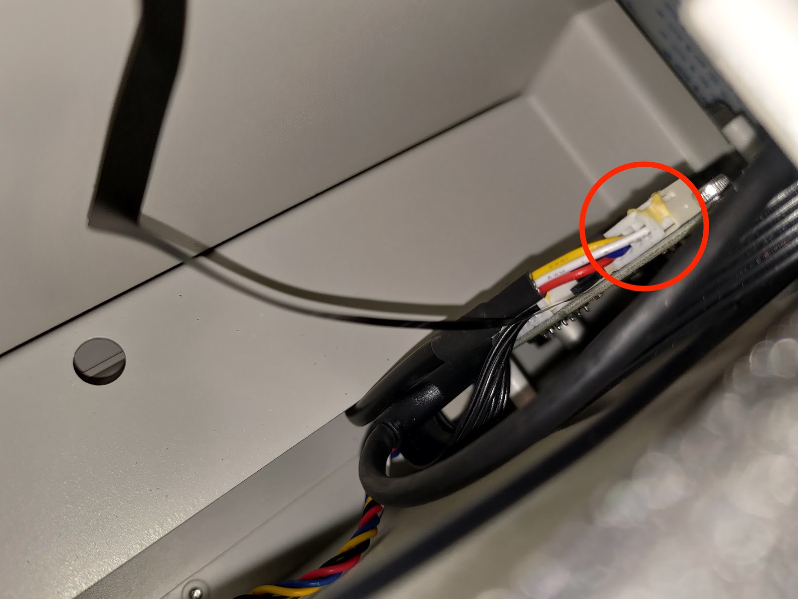
Step 18:
Push back the plate and screw the screws. (T8 screw x 8pcs)
Step 19
Since the steps above involved moving the door cover and camera, please perform the camera calibration as the final step before resuming the machine's use.
You can refer to this page: Camera Calibration.
#End
Comments
0 comments
Please sign in to leave a comment.