Description
This article will guide you through how to adjust the optical path.
If you are uncertain about whether your optical path needs to be adjusted, please use the link below to inspect your path first. Optical Path Inspection
Note:
Some photos used in this article are HEXA's, but the mechanism for Beambox 2 is the same.
Signs of a Misaligned Optical Path
- Not able to cut through the materials using the default power rate & speed in Beam Studio.
- Having bad engraving results that the engraving patterns in a certain area are lighter or deeper than other areas, or it is getting lighter or deeper in a certain direction.
- The cut section on the material is not vertical after cutting.
|
Step 1
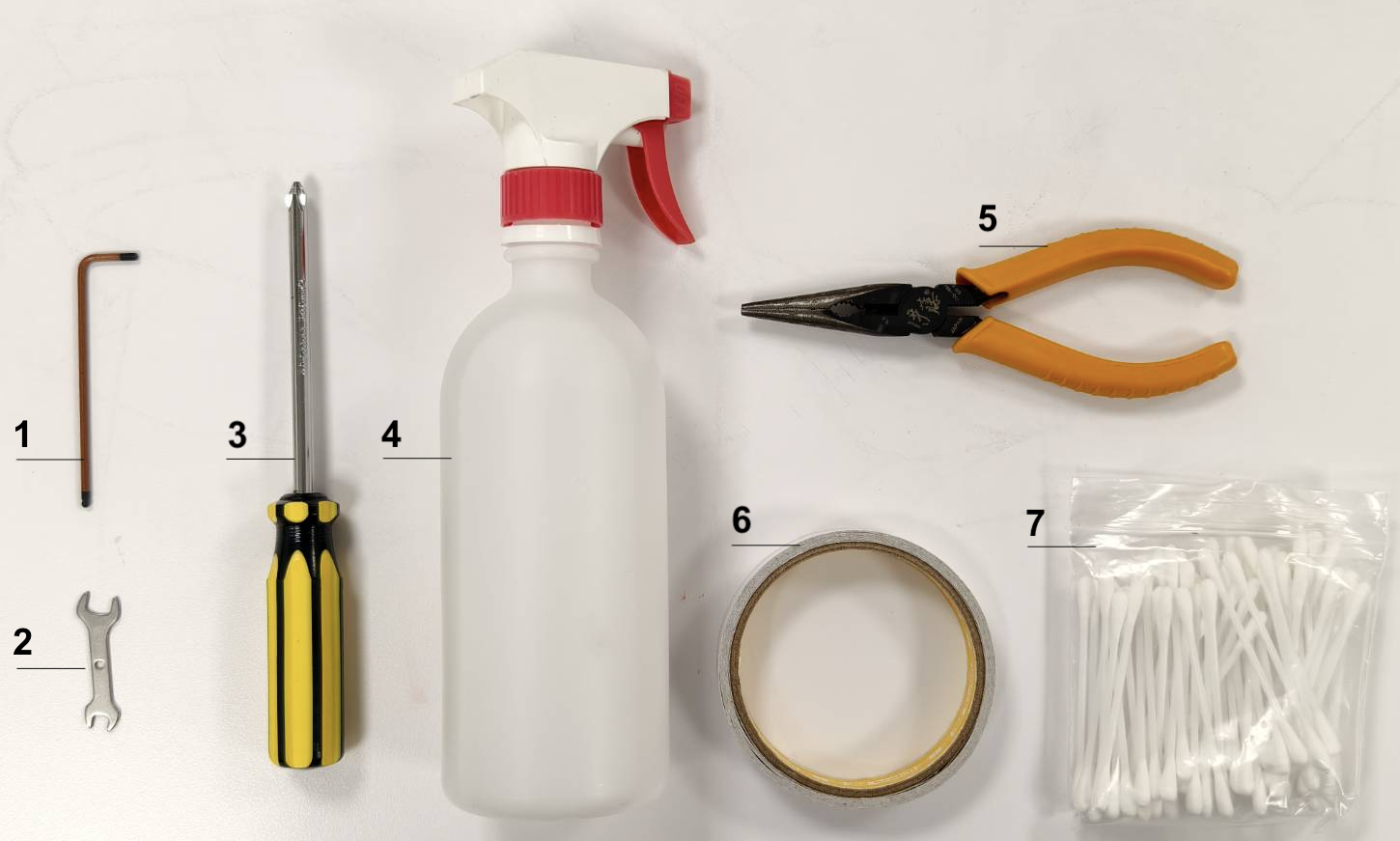
Please prepare the following tools.
- 2.5mm hexagonal wrench
- Double-head wrench
- Phillips screwdriver
- Sanitizer spray / Alcohol spray
- Pliers
- Double-sided tape
- Cotton swabs
|
Step 2
Please get familiar with how to make a pulse safely.
A. Turn on the machine.
B. Close the lid.
C. Enter Maintain mode and wait til the homing process is done.
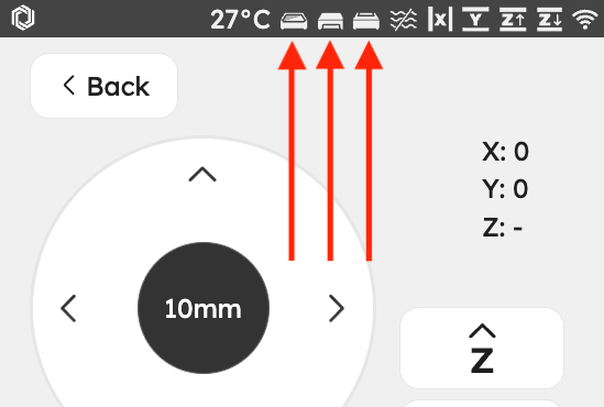
(Make sure the door, back cover, and bottom icons are closed, or you won't be able to make a pulse.)
D. Find the Pulse button.
E. One press = one pulse, two presses = two pulses, and so on.
⚠︎ Please always make pulses when the door lid and back cover are closed.
|
|
 |
Step 3
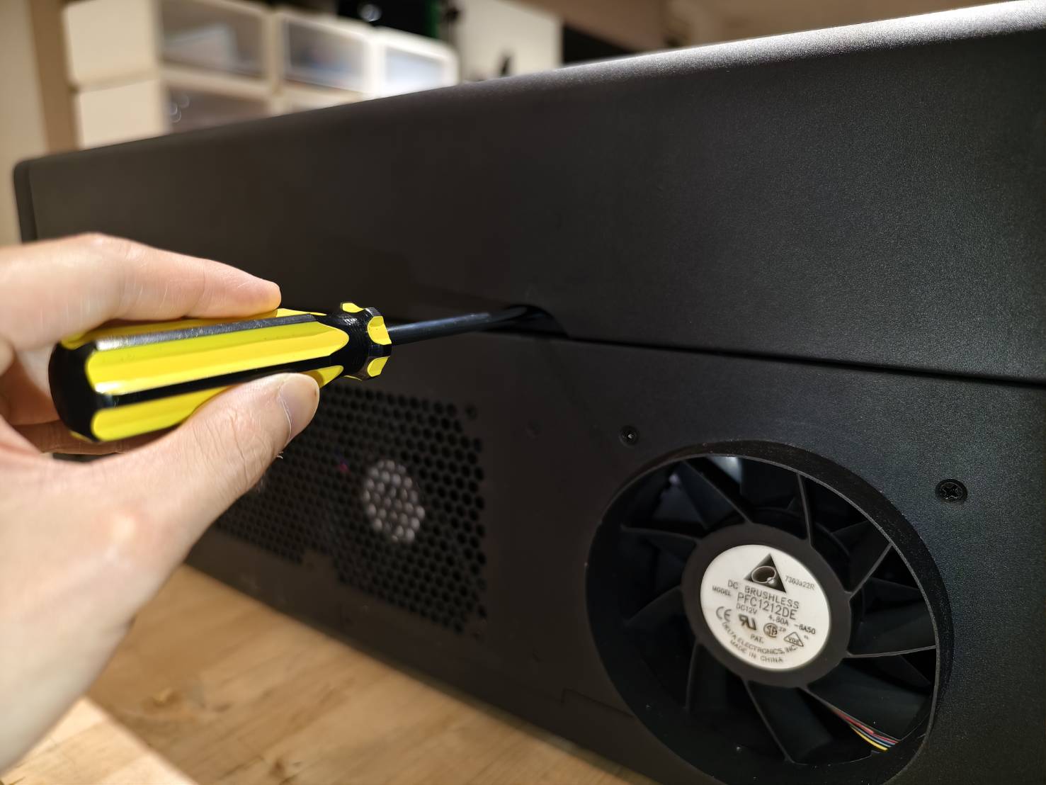
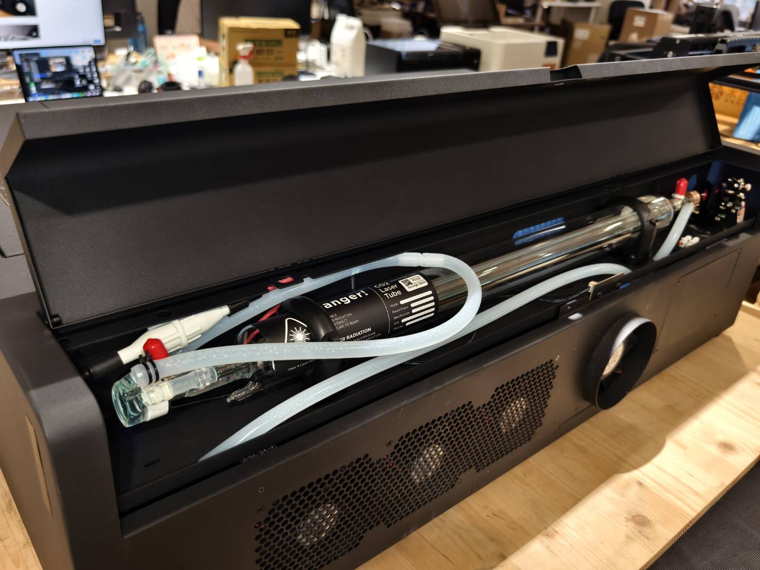
Use a screwdriver to unscrew the screws at the back of the machine, and the back cover can be opened afterward.
Step 4
Please get familiar with the locations:
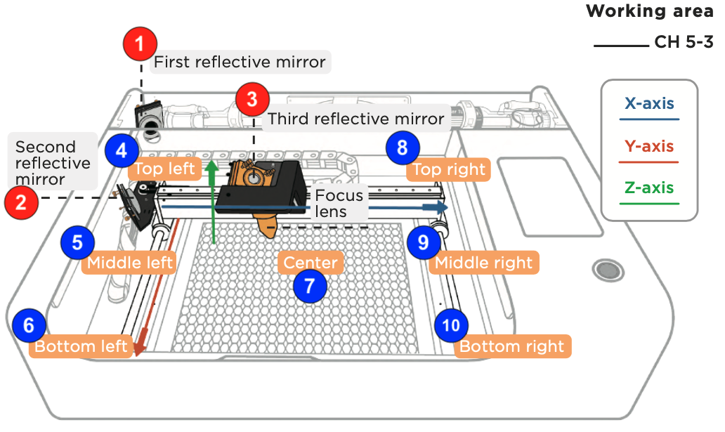
|
1
|
First mirror location |
It's where to adjust the path from the 1st to 2nd mirror.
(Open the back cover to find the 1st mirror.)
|
|
2
|
Second mirror location |
It's where to adjust the path from the 2nd to 3rd mirror. |
|
3
|
Third mirror location |
It's where to adjust the vertical path from 3rd mirror to the bed. |
|
4
|
Top-left location of the bed |
It's where the laser head will be moved to during the process. |
|
5
|
Middle-left location of the bed |
It's where the laser head will be moved to during the process. |
|
6
|
Bottom-left location of the bed |
It's where the laser head will be moved to during the process. |
|
7
|
Center of the bed |
It's where the laser head will be moved to during the process. |
|
8
|
Top-right location of the bed |
It's where the laser head will be moved to during the process. |
|
9
|
Middle-right location of the bed |
It's where the laser head will be moved to during the process. |
|
10
|
Bottom-right location of the bed |
It's where the laser head will be moved to during the process. |
Step 5
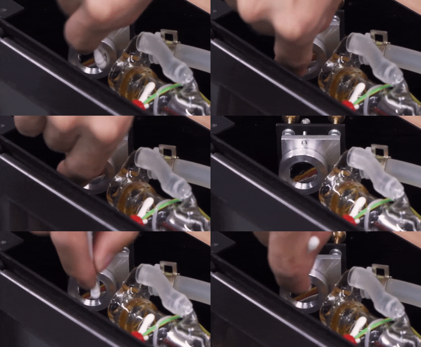
Please clean all the mirrors and lenses using the instructions in the link below.
Mirrors and Lens Cleaning
Step 6
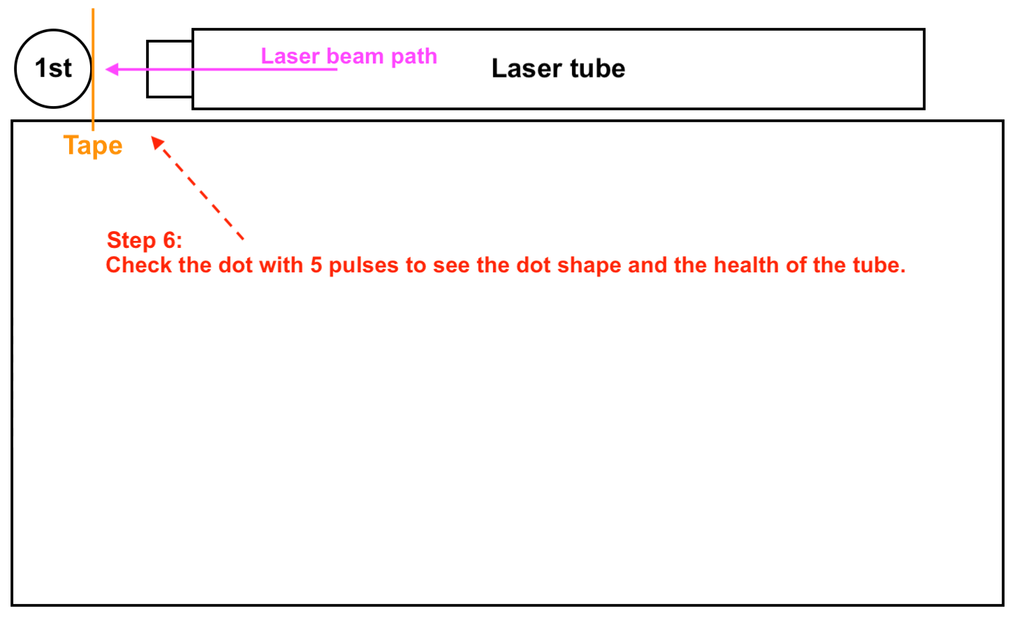
Check the laser dot on the 1st mirror.
This step checks if the laser tube and the machine are in good condition.
Step overview:
|
Determine your result and the next action to take:
-
The result is bad, or it doesn't have any marks >> Contact Customer Service
-
Possible Cause:
- The laser tube is broken and must be replaced.
- The laser power supply is broken and must be replaced.
|
Step 7
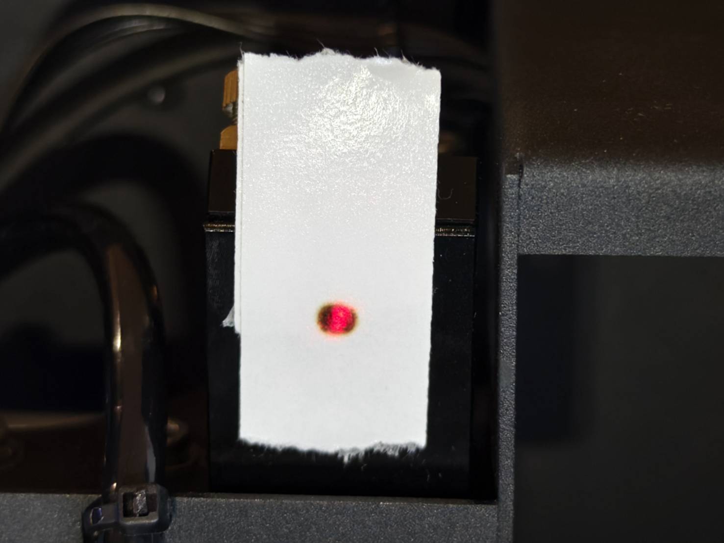
Check if the red laser dot and the burnt mark overlap.
This step checks if the paths of the red laser and the actual CO2 laser match and are aligned.
If they are not aligned, adjust the red light emitter with a 2.5mm Allen key.
- Open the door.
- Place a two-layer, double-sided tape on the third mirror entrance.
- Enter the control mode and loosen the motor.
- Move the laser head to the bottom-right corner.
- Make sure the red laser is turned on.
- Close the door.
- Make 3 pulses.
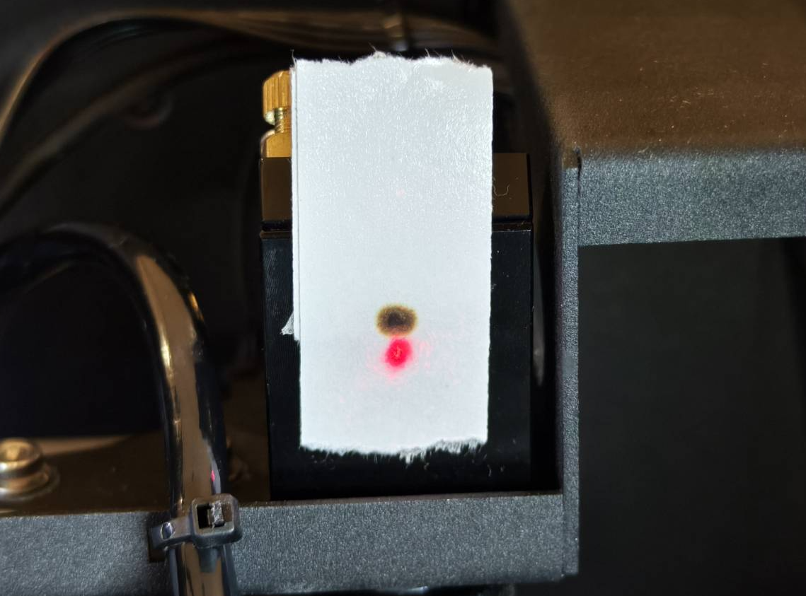
- Check if the red laser dot and the burnt mark overlap.
- Adjust the red laser if necessary.
|
Good Example - Overlapped
|
Bad Example - Not Overlapped
|
 |
|
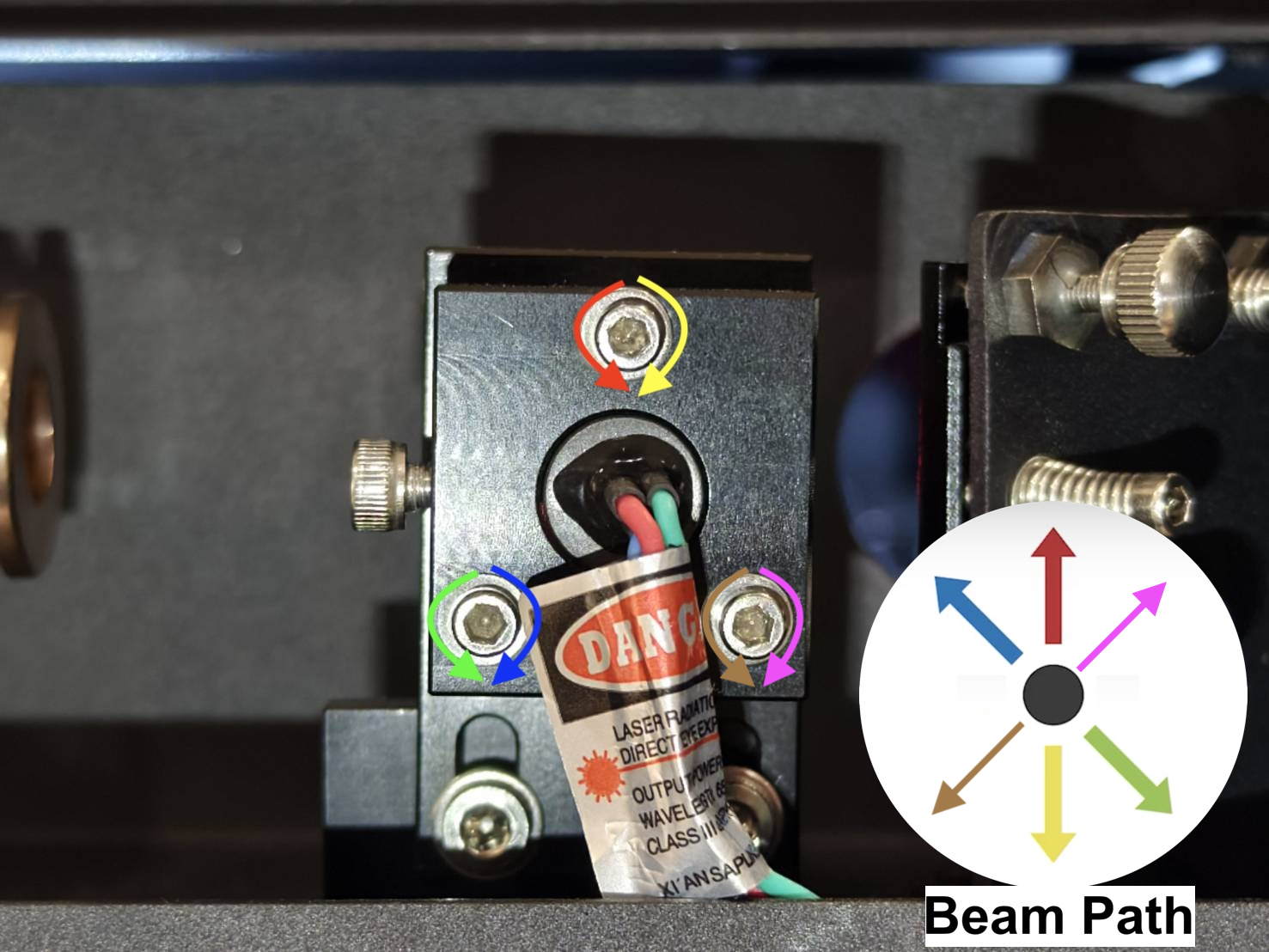
| Screws and Beam Path of The Red Light Emitter |
|
|
Step 8
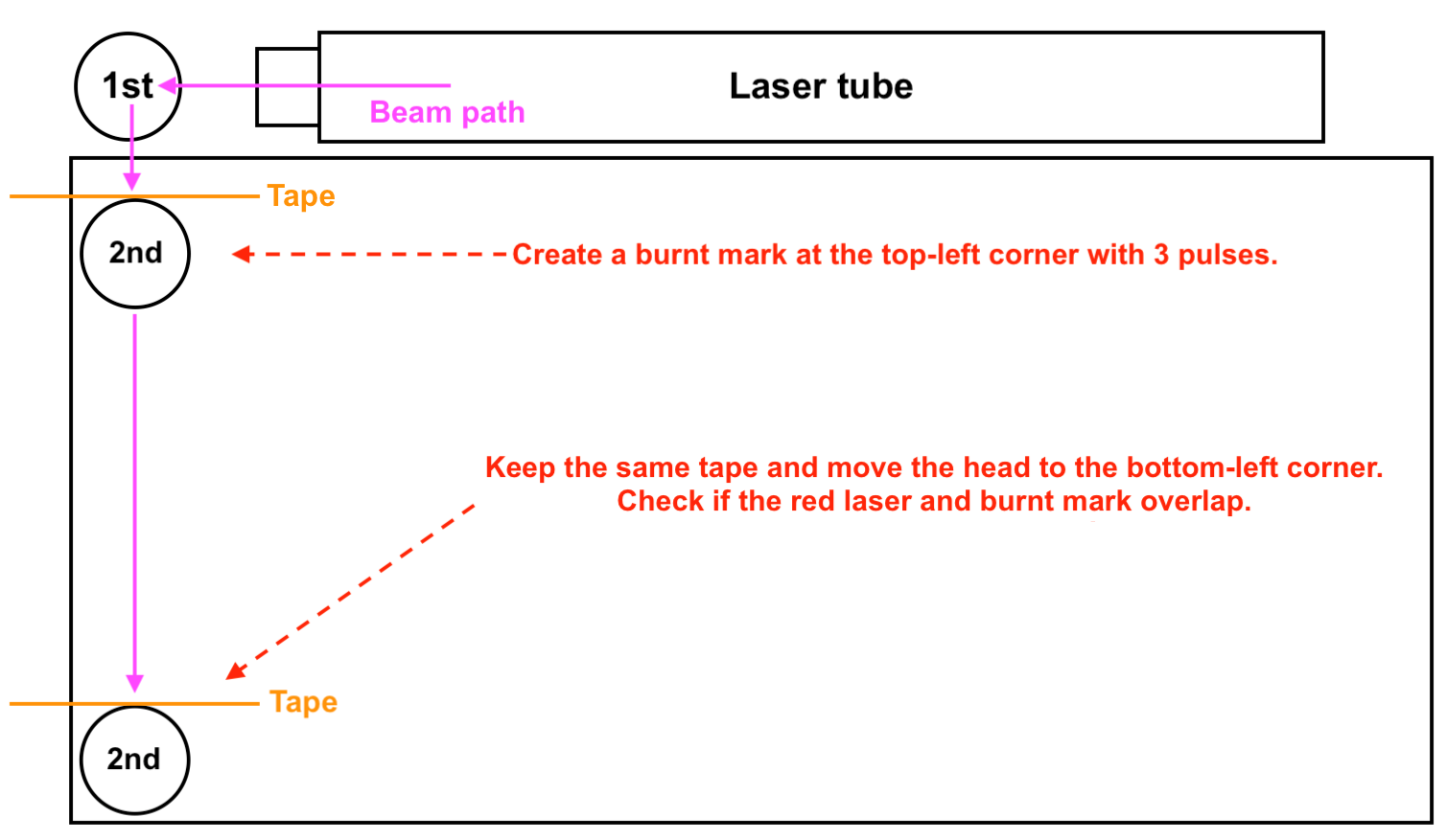
This step checks if the path is aligned from the 1st mirror to the 2nd mirror.
|
Step overview:
|
|
Actual Steps:
- Remove the tape and place a new two-layer, double-sided tape on the 2nd mirror.
- Move the laser head to the top-left corner.
- Close the door and make 3 pulses.
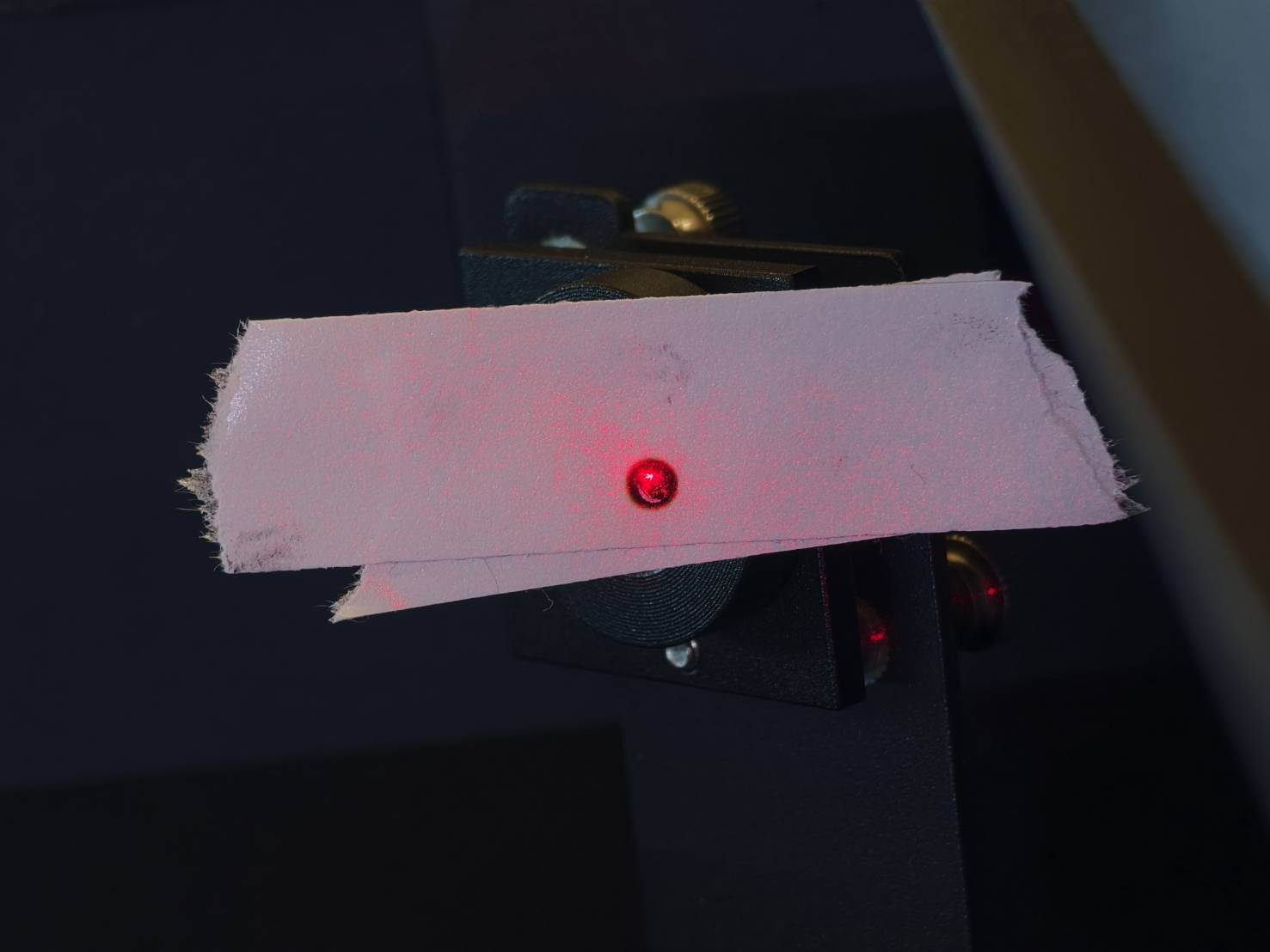
- Visibly check if the red laser and burnt mark overlap.
|
|
|
Good Example - Overlapped
|
|
Bad Example - Not Overlapped
|
|
|
Determine your result and the next action to take:
- Good result - Overlapped >> Step 9
|
Step 8.1
This step will teach you how to align the path from the 1st mirror to the 2nd mirror by adjusting the screws on the 1st mirror.
- There are three screws on the 1st mirror, and rotating them clockwise or counter-clockwise will change the beam path meaning the red laser dot's position will change.
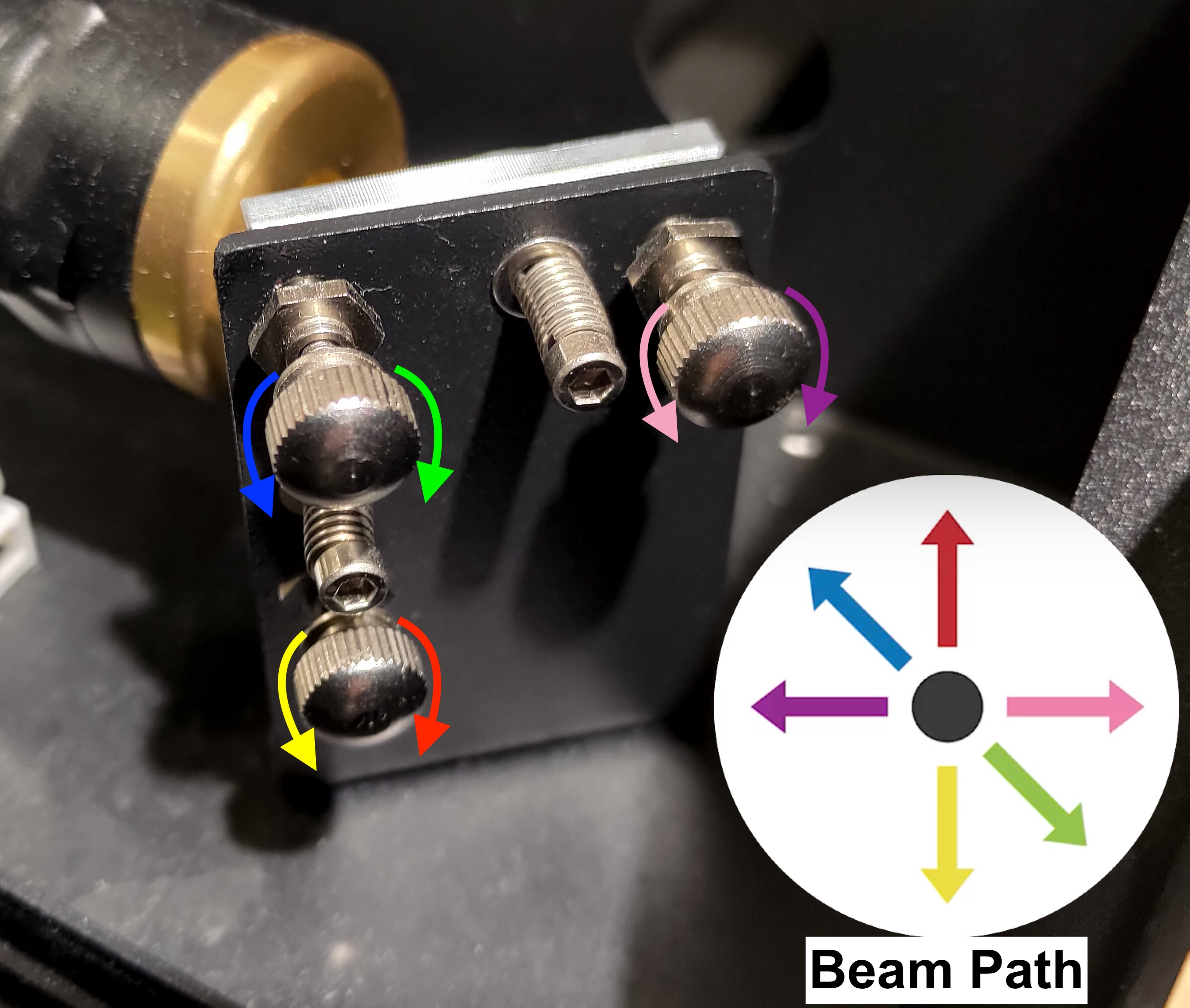
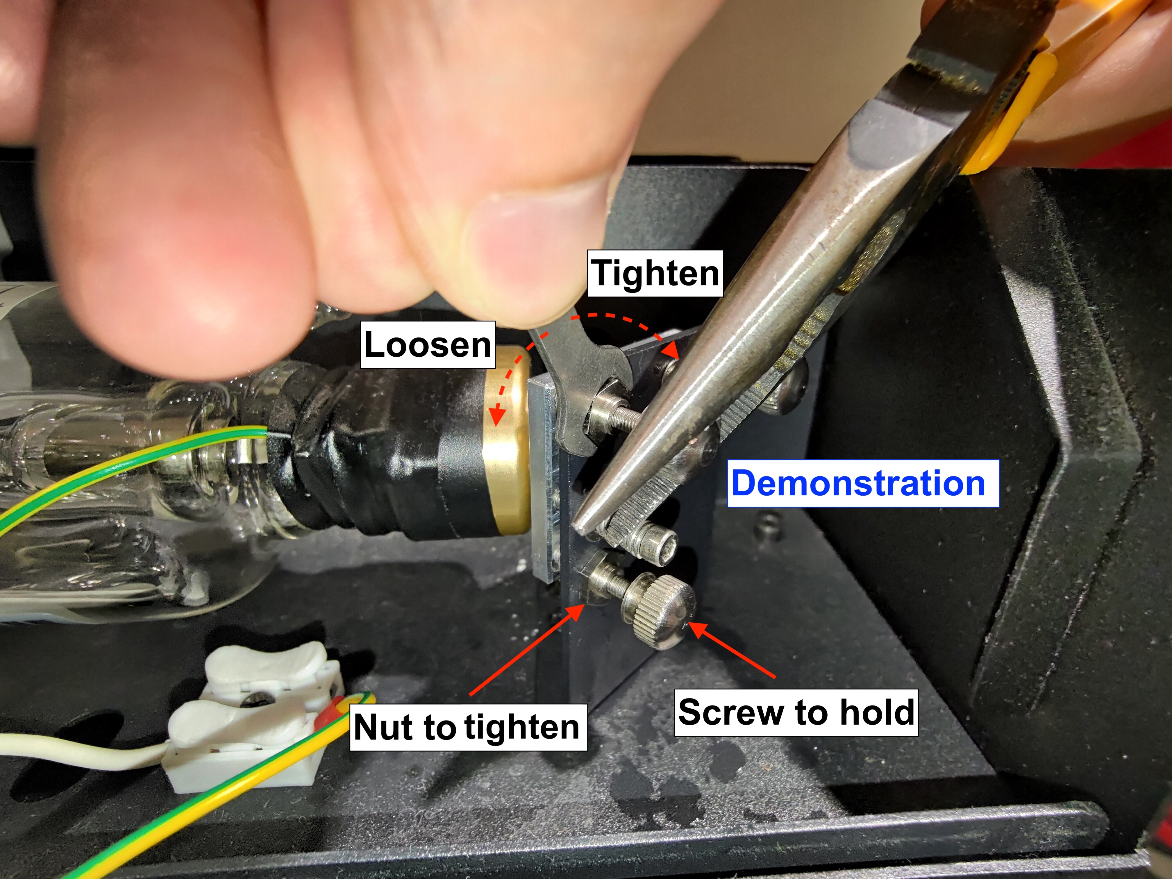
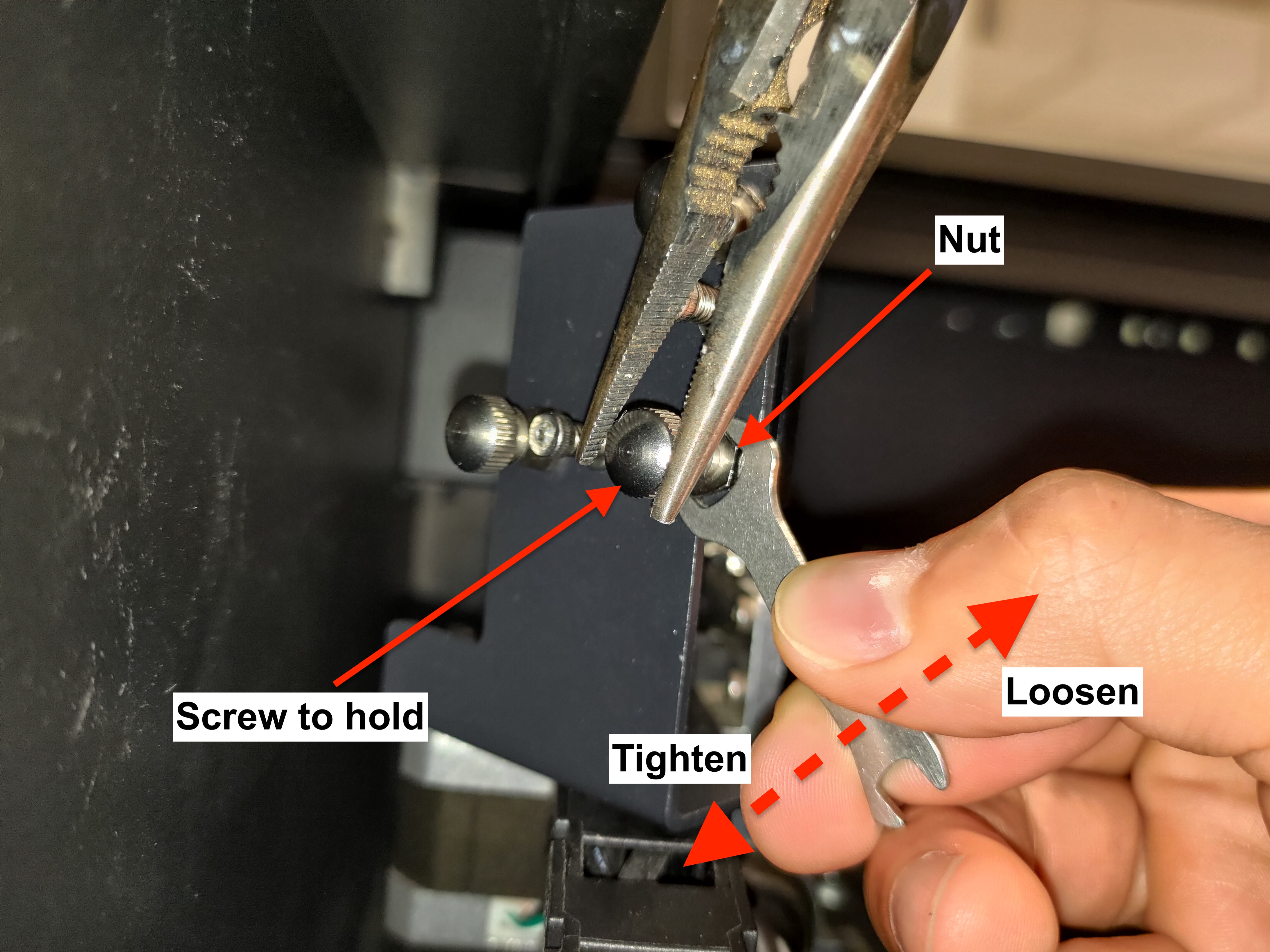
- Please learn how to loosen the nut properly:
Firstly, spray the alcohol on the nuts to melt the gel or glue and wait for a few seconds.
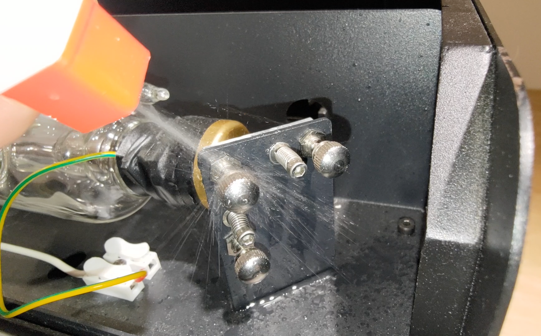
- Next, use the pliers to hold the screw, then loosen the nut with the double-head wrench by turning it counterclockwise.
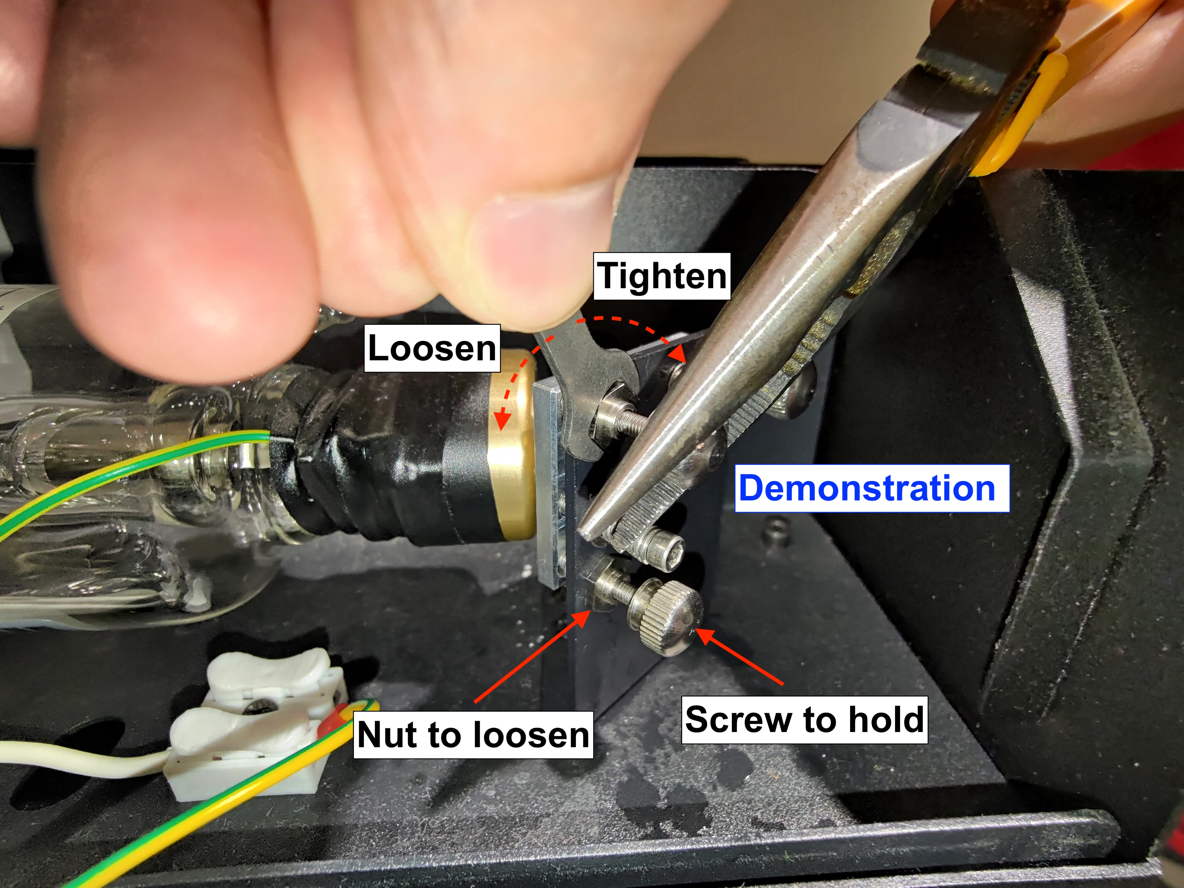
-
Demonstration
(Please note that the screws in the video have been loosened before recording.)
|
- Determine the position of your red laser dot, target the screw, and its direction of rotation.
Please see the photo below and find the number that is similar to your red laser dot's position: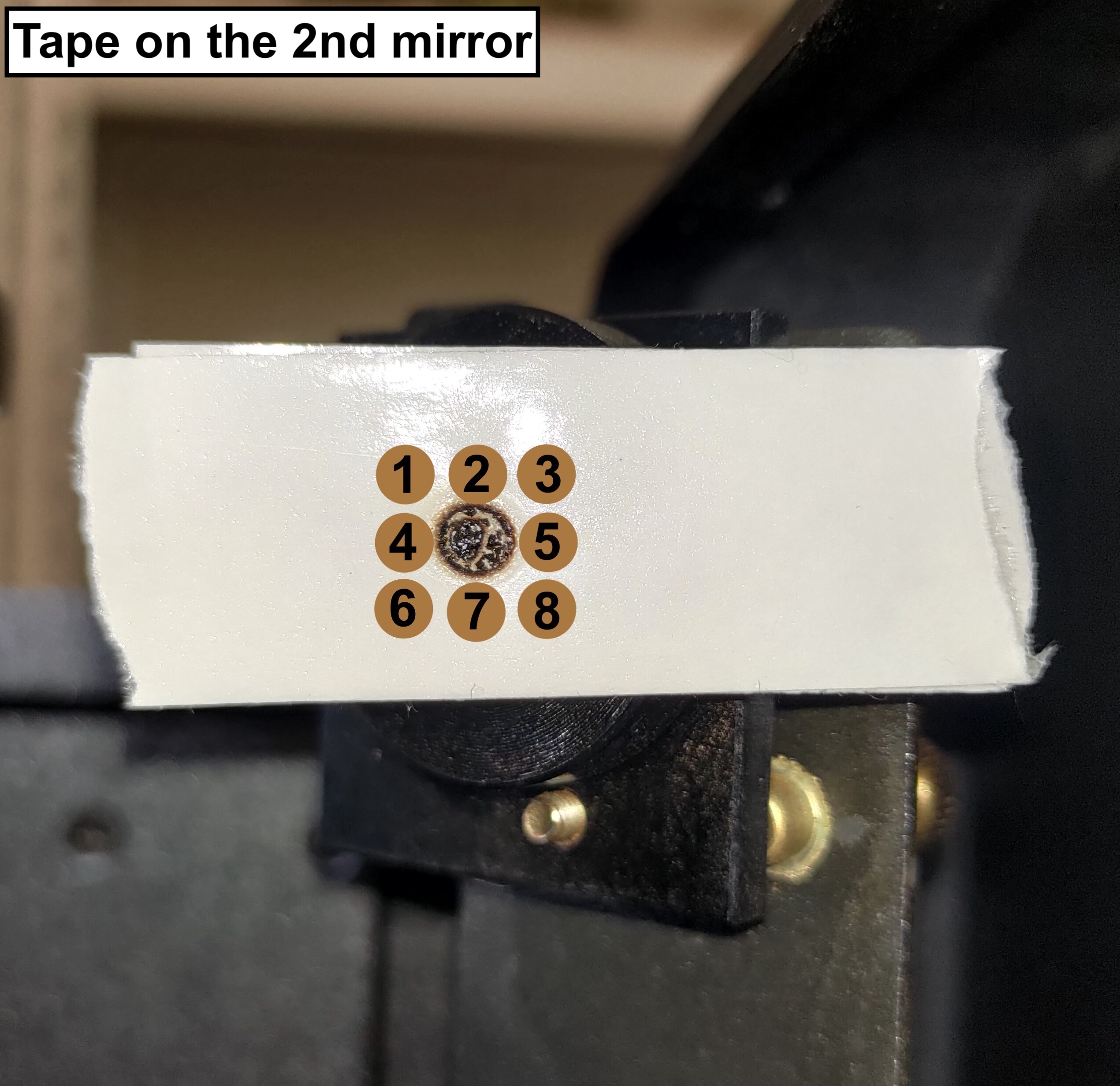
-
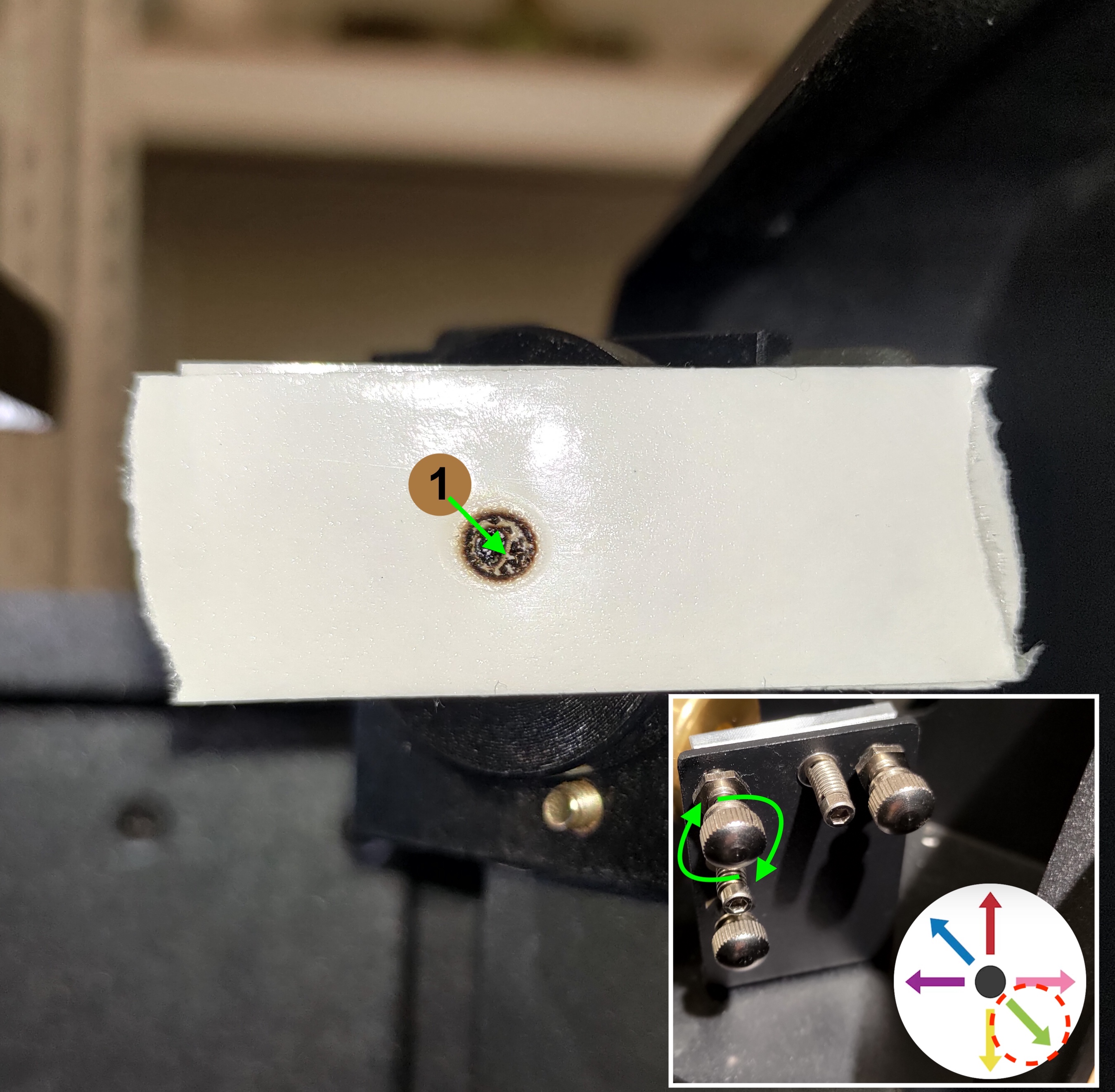
For #1:
The red laser dot needs to go down to the right in order to overlap the first dot
The top-left screw will need to be rotated clockwise. Please refer to the photo below.
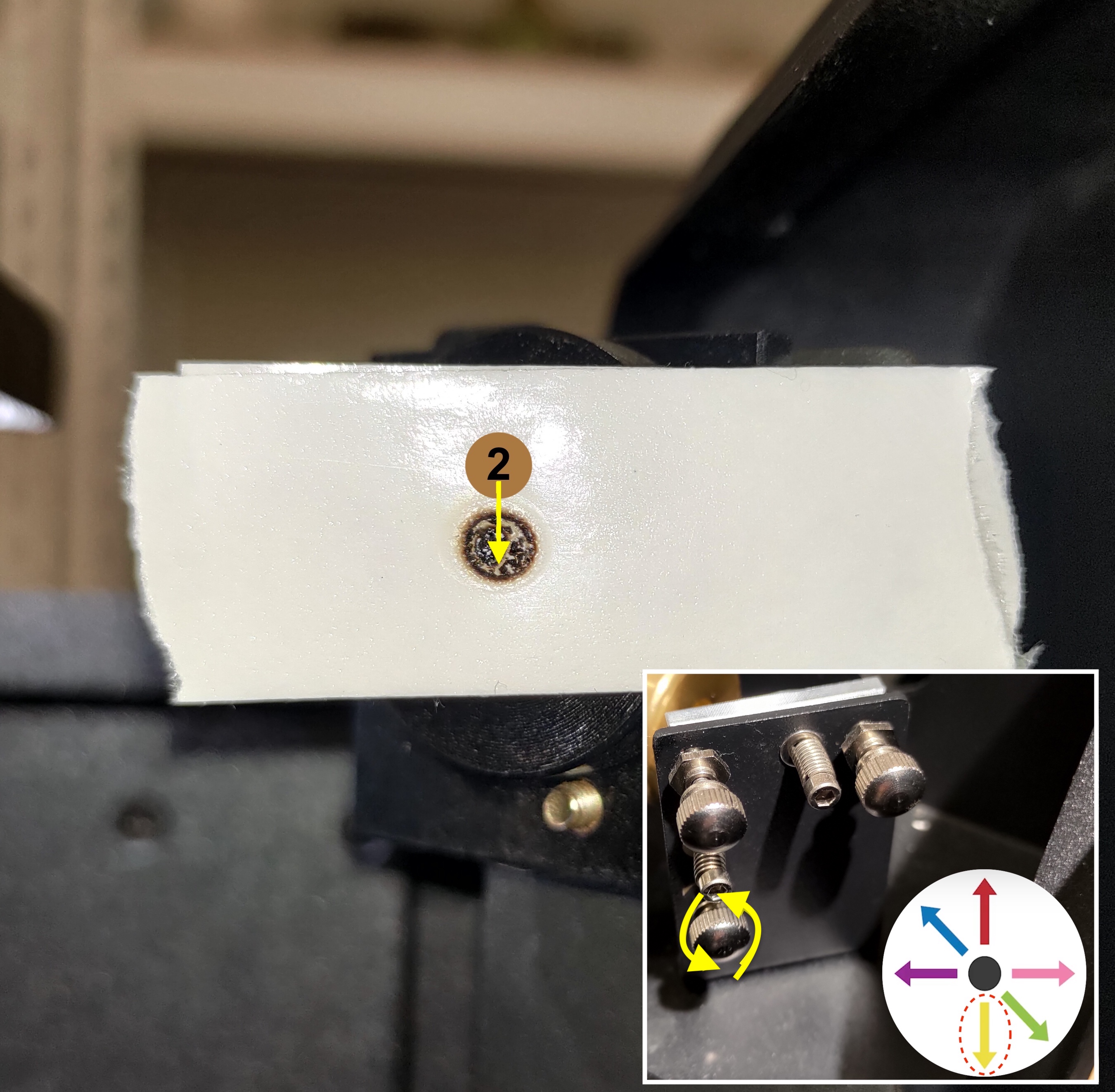
For #2:
The red laser dot needs to go straight down in order to overlap the first dot.
The bottom-left screw will need to be rotated counter-clockwise. Please refer to the photo below.
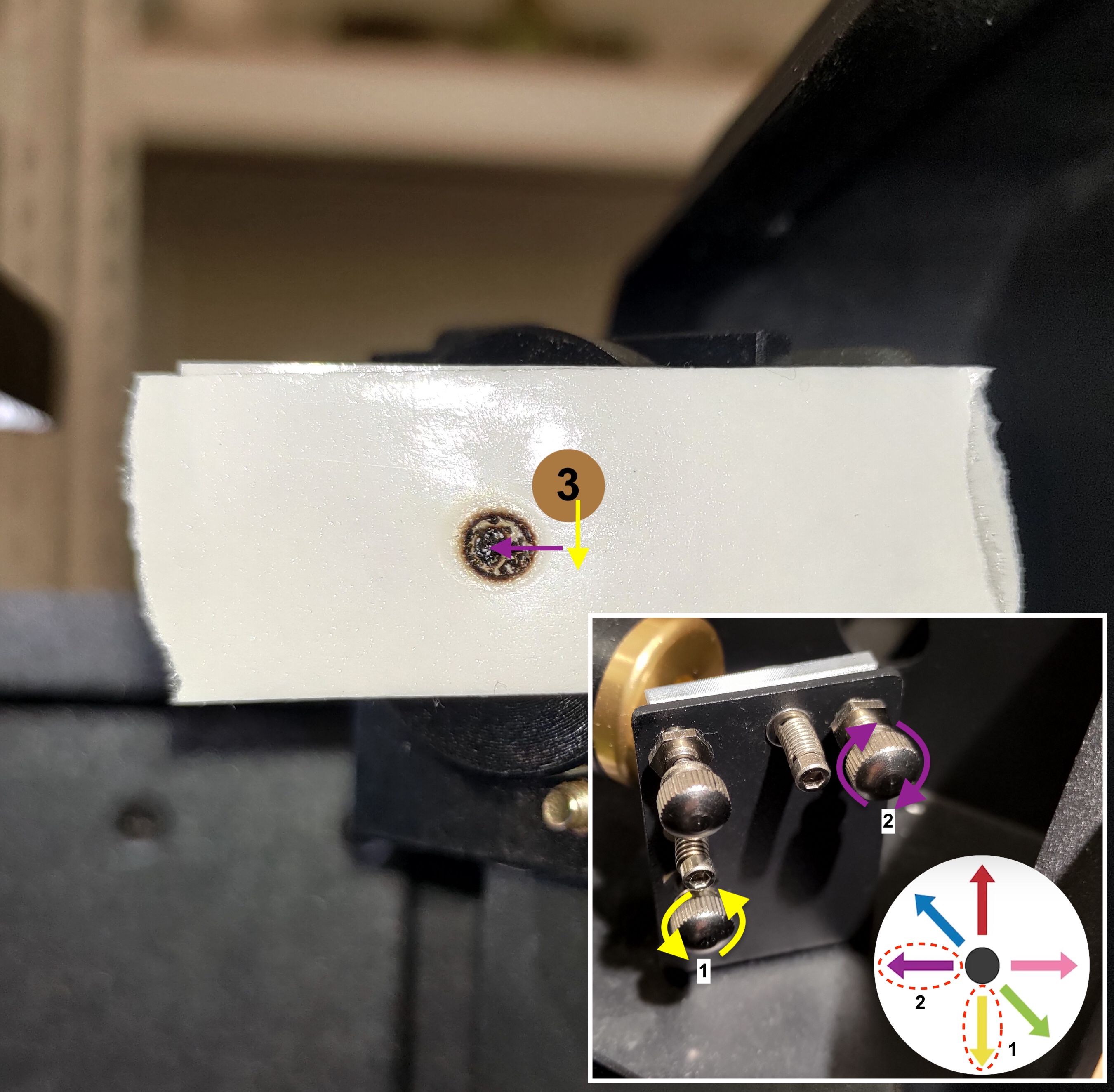
For #3:
The red laser dot needs to go down first and then go left in order to overlap the first dot.
The bottom-left screw will need to be rotated counter-clockwise to make the dot go down.
The top-right screw will need to be rotated clockwise to make the dot go left.
Please refer to the photo below.
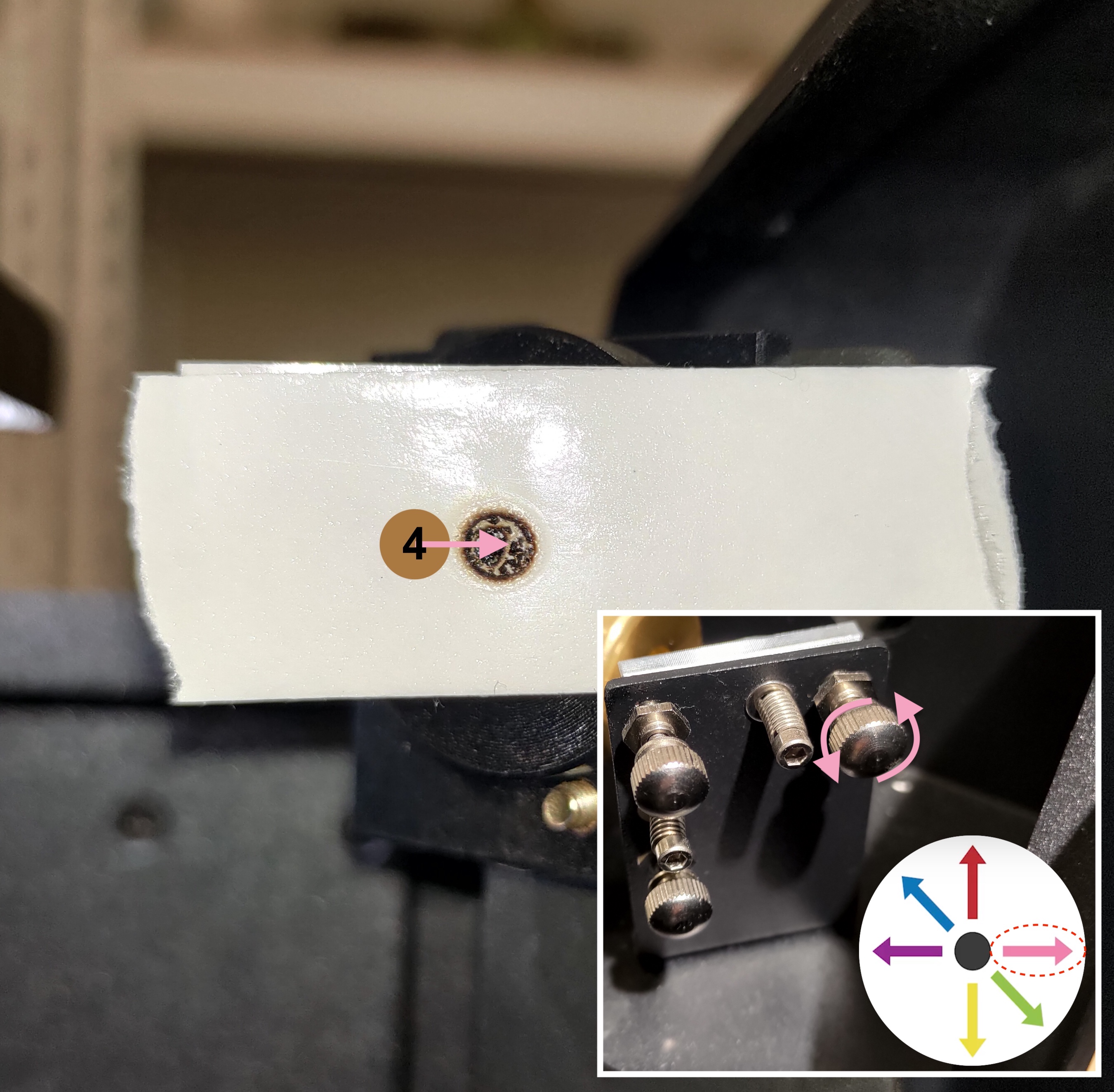
For #4:
The red laser dot needs to go right in order to overlap the first dot.
The top-right screw will need to be rotated counter-clockwise. Please refer to the photo below.
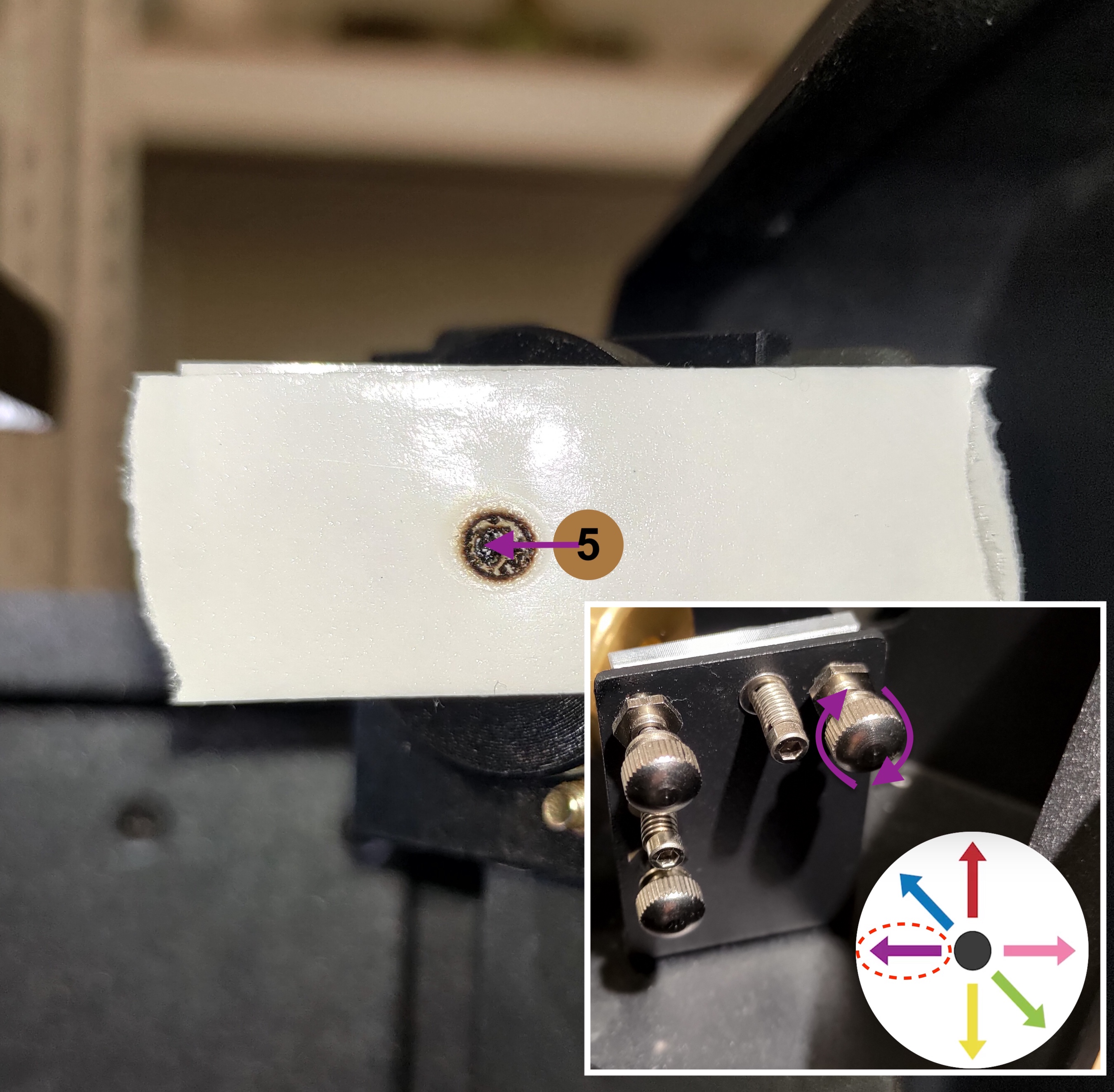
For #5:
The red laser dot needs to go left in order to overlap the first dot.
The top-right screw will need to be rotated clockwise. Please refer to the photo below.
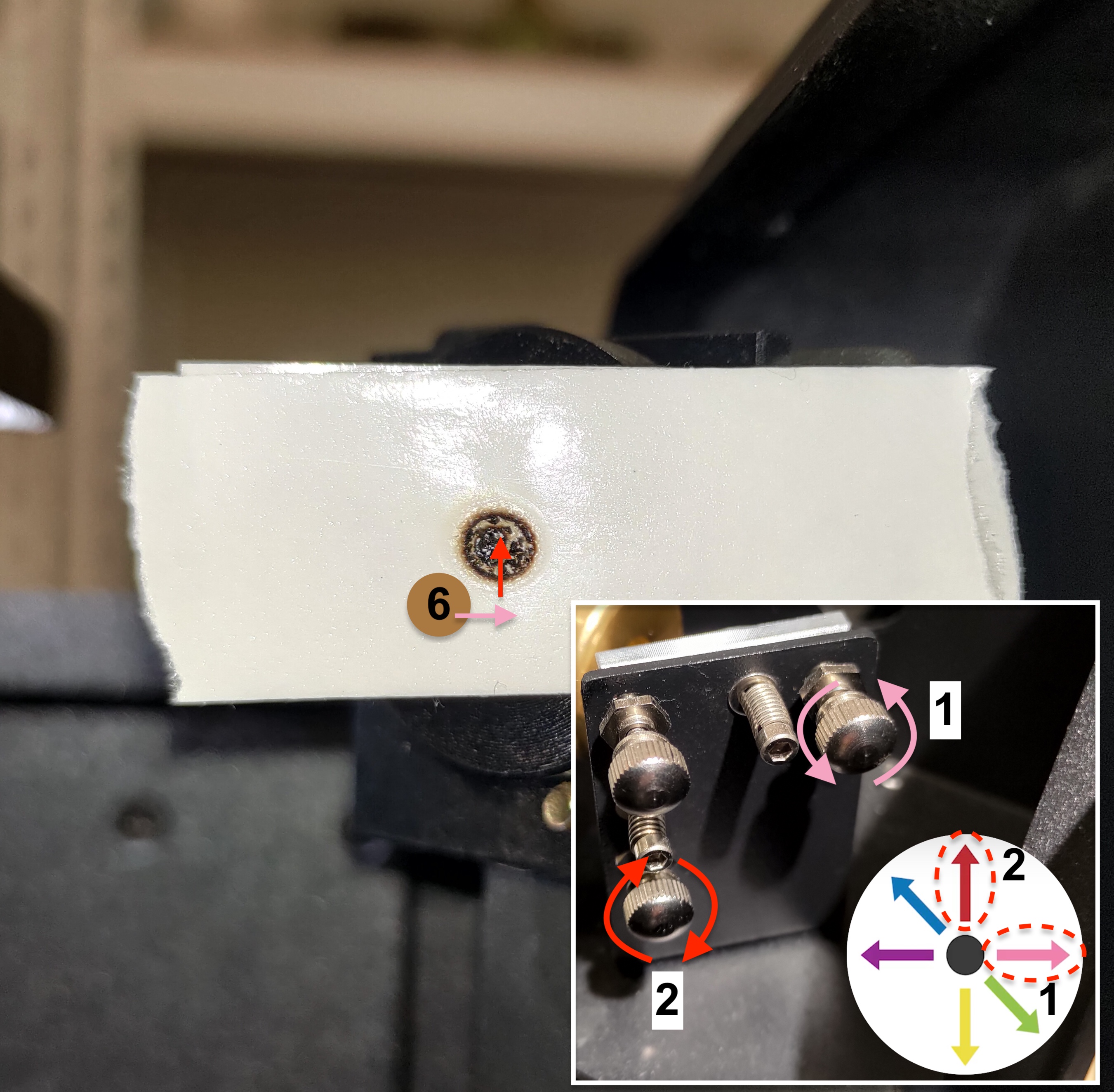
For #6:
The red laser dot needs to go right first and then go up in order to overlap the first dot.
The top-right screw will need to be rotated counter-clockwise to make the dot go right.
The bottom-left screw will need to be rotated clockwise to make the dot go up.
Please refer to the photo below.
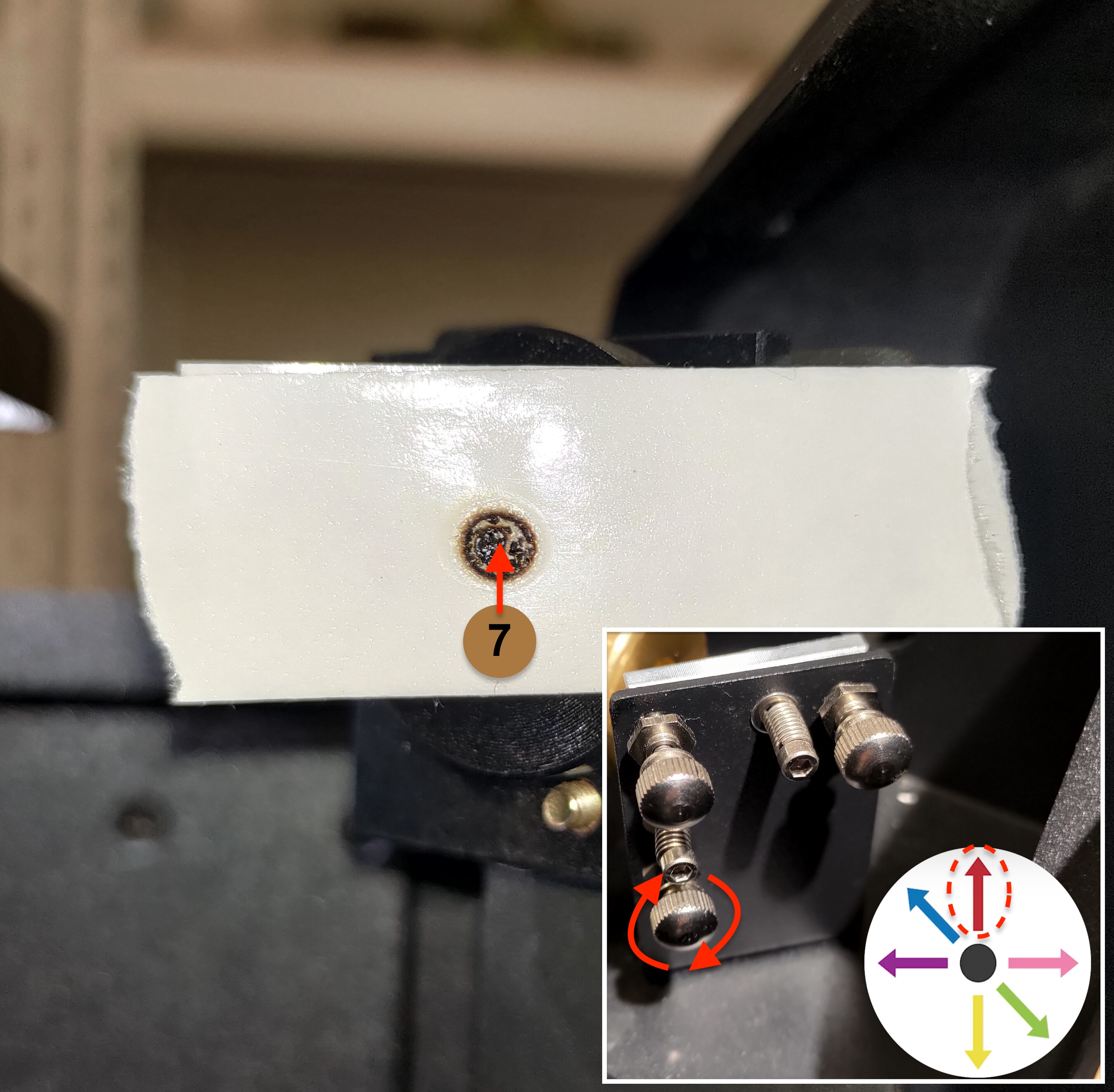
For #7:
The red laser dot needs to go straight up in order to overlap the first dot.
The bottom-left screw will need to be rotated clockwise. Please refer to the photo below.
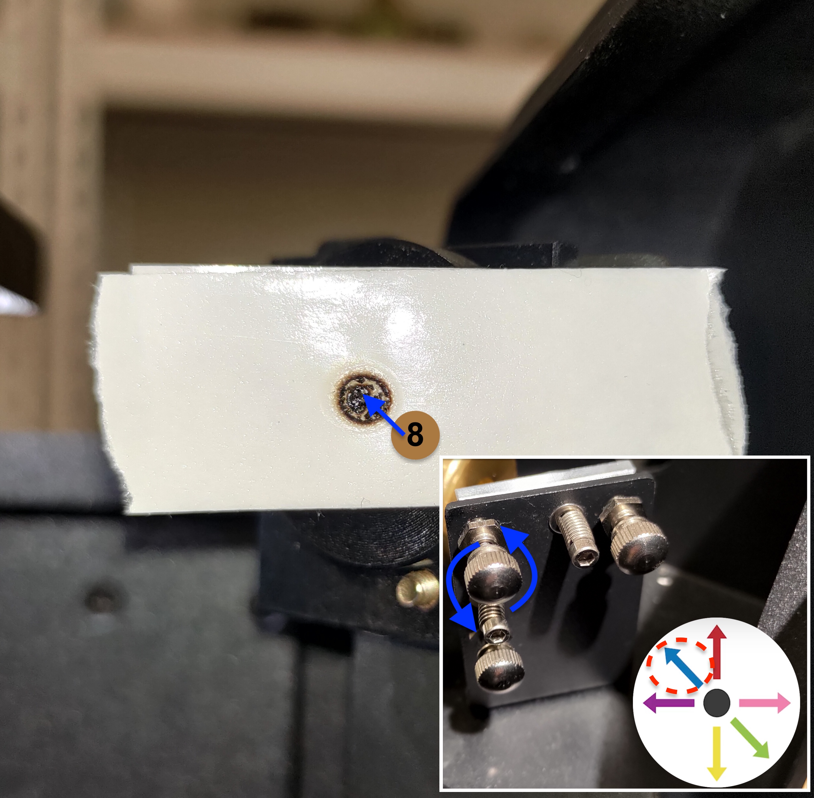
For #8:
The red laser dot needs to go up to the left in order to overlap the first dot
The top-left screw will need to be rotated counter-clockwise. Please refer to the photo below.
|
- Please tighten the nut after adjusting the screw by turning it clockwise.
|
Step 9
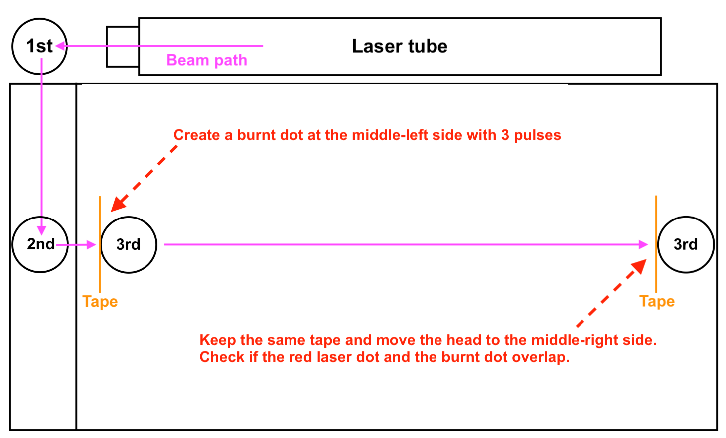
This step checks if the path is aligned from the 2nd mirror to the 3rd mirror.
|
Step overview:
|
|
Actual Steps:
- Remove the tape and place a new two-layer, double-sided tape on the third mirror entrance.
- Move the laser head to the middle left side.
- Close the door and make 3 pulses.
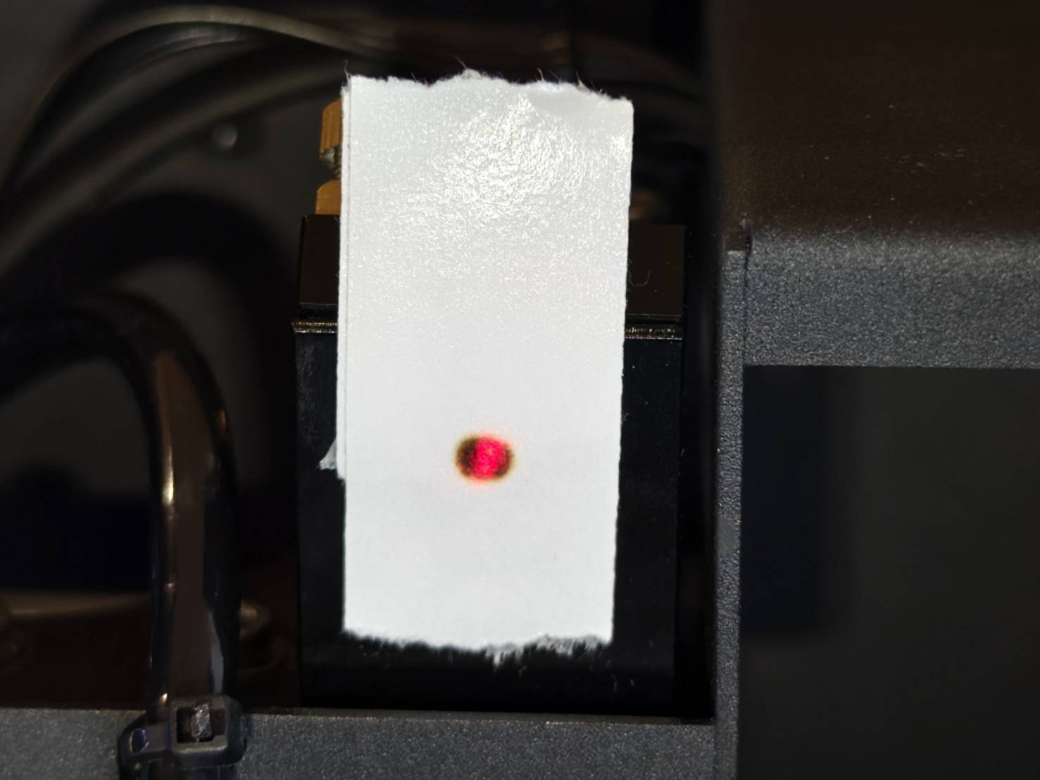
- Visibly check if the red laser and burnt mark overlap.
|
|
|
Good Example - Overlapped
|
|
Bad Example - Not Overlapped
|
|
|
Determine your result and the next action to take:
- Good result - Overlapped >> Step 10
|
Step 9.1
This step will teach you how to align the path from the 2nd mirror to the 3rd mirror by adjusting the screws on the 2nd mirror.
-
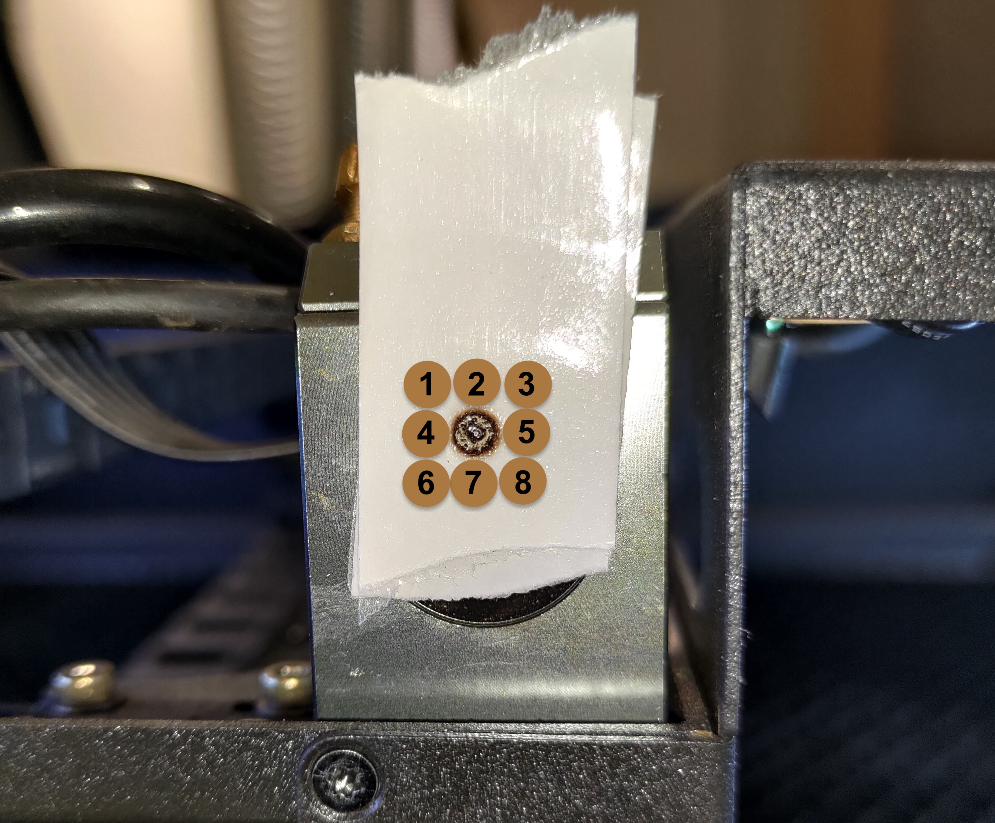
Determine the position of your red laser dot, target the screw, and its direction of rotation.
Please see the photo below and find the number that is similar to your red laser dot's position.
-
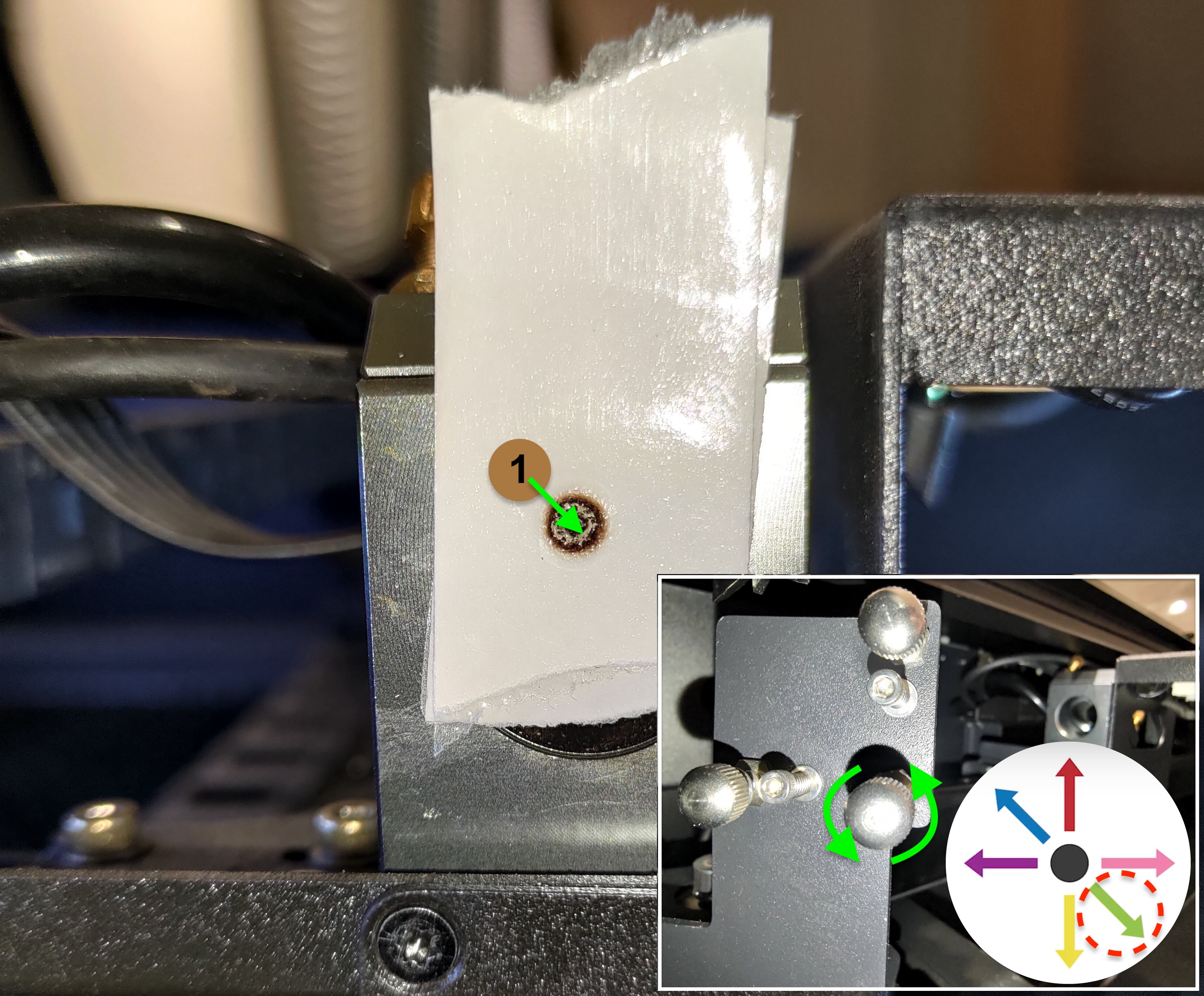
For #1:
The red laser dot needs to go down to the right to overlap the first dot.
The bottom-right screw will need to be rotated counter-clockwise.
Please refer to the photo below.
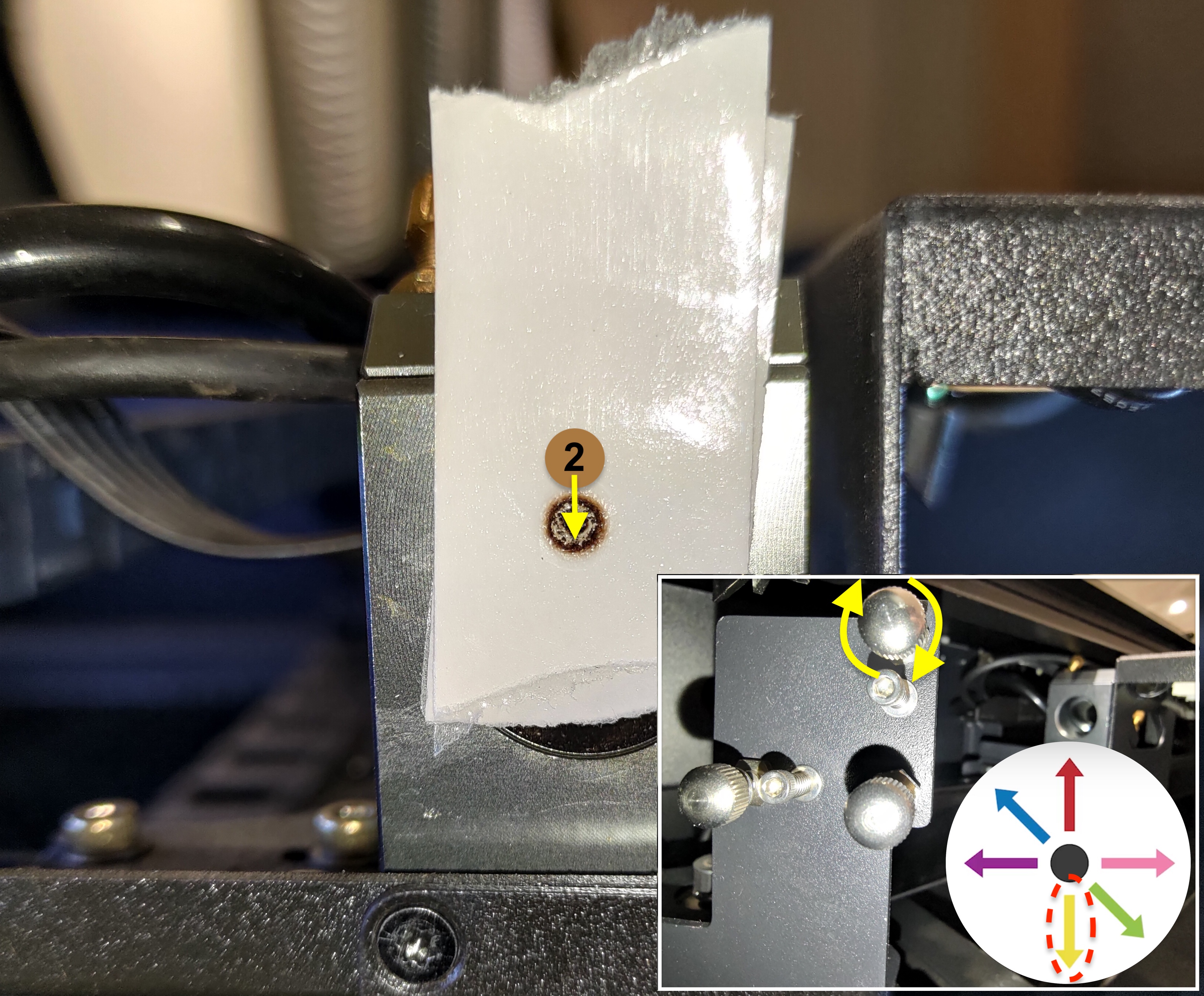
For #2:
The red laser dot needs to go straight down to overlap the first dot.
The top-right screw will need to be rotated clockwise. Please refer to the photo below.
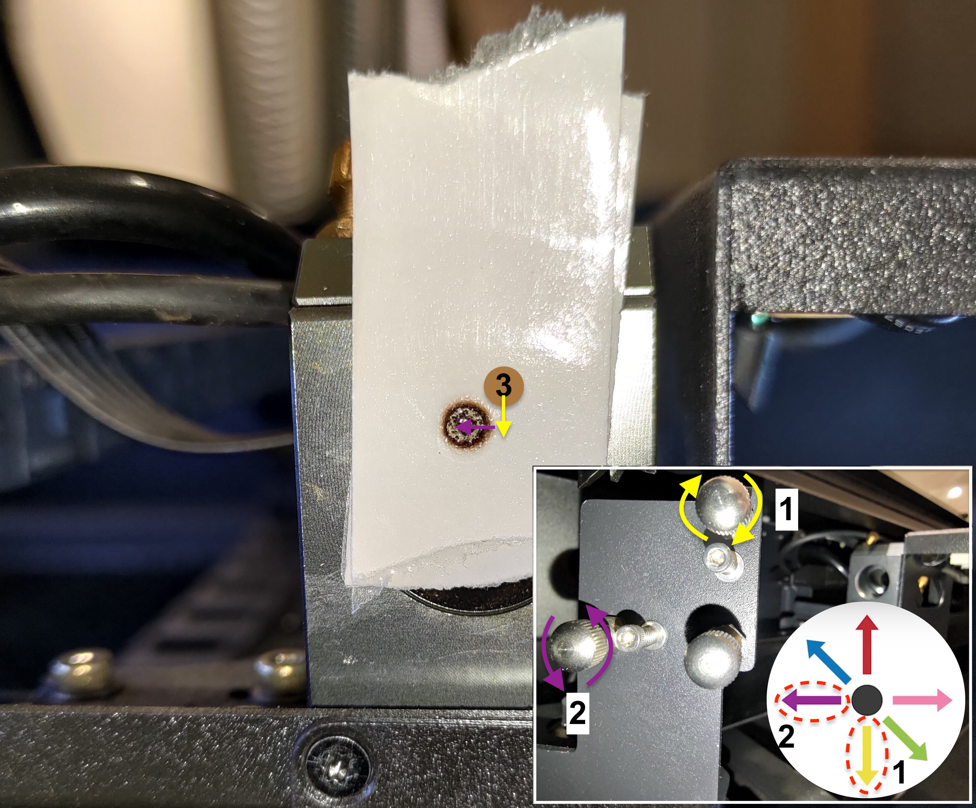
For #3:
The red laser dot needs to go down first and then go left in order to overlap the first dot.
The top-right screw will need to be rotated clockwise to make the dot go down.
The bottom-left screw will need to be rotated counter-clockwise to make the dot go left.
Please refer to the photo below.
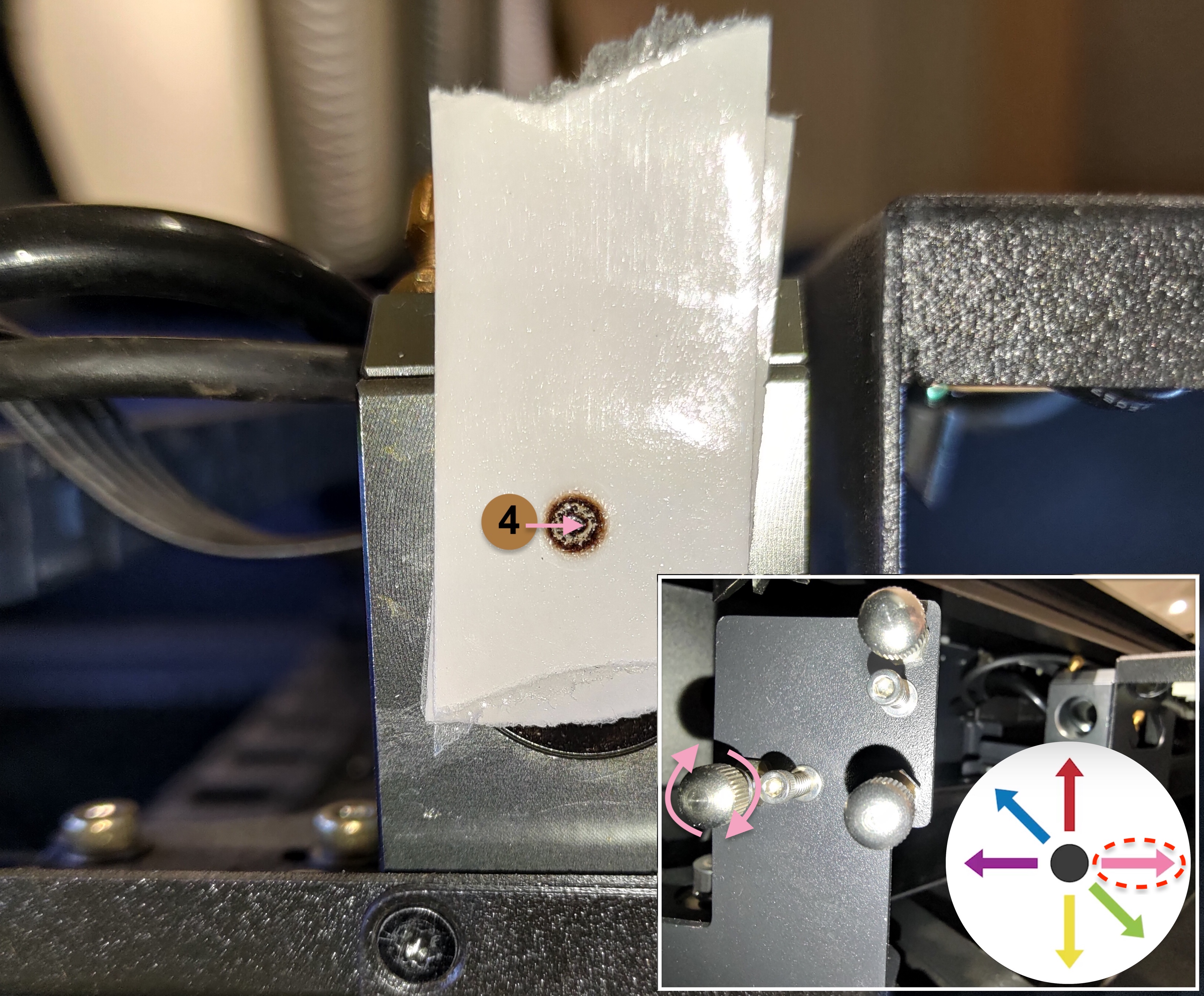
For #4:
The red laser dot needs to go right in order to overlap the first dot.
The bottom-left screw will need to be rotated clockwise. Please refer to the photo below.
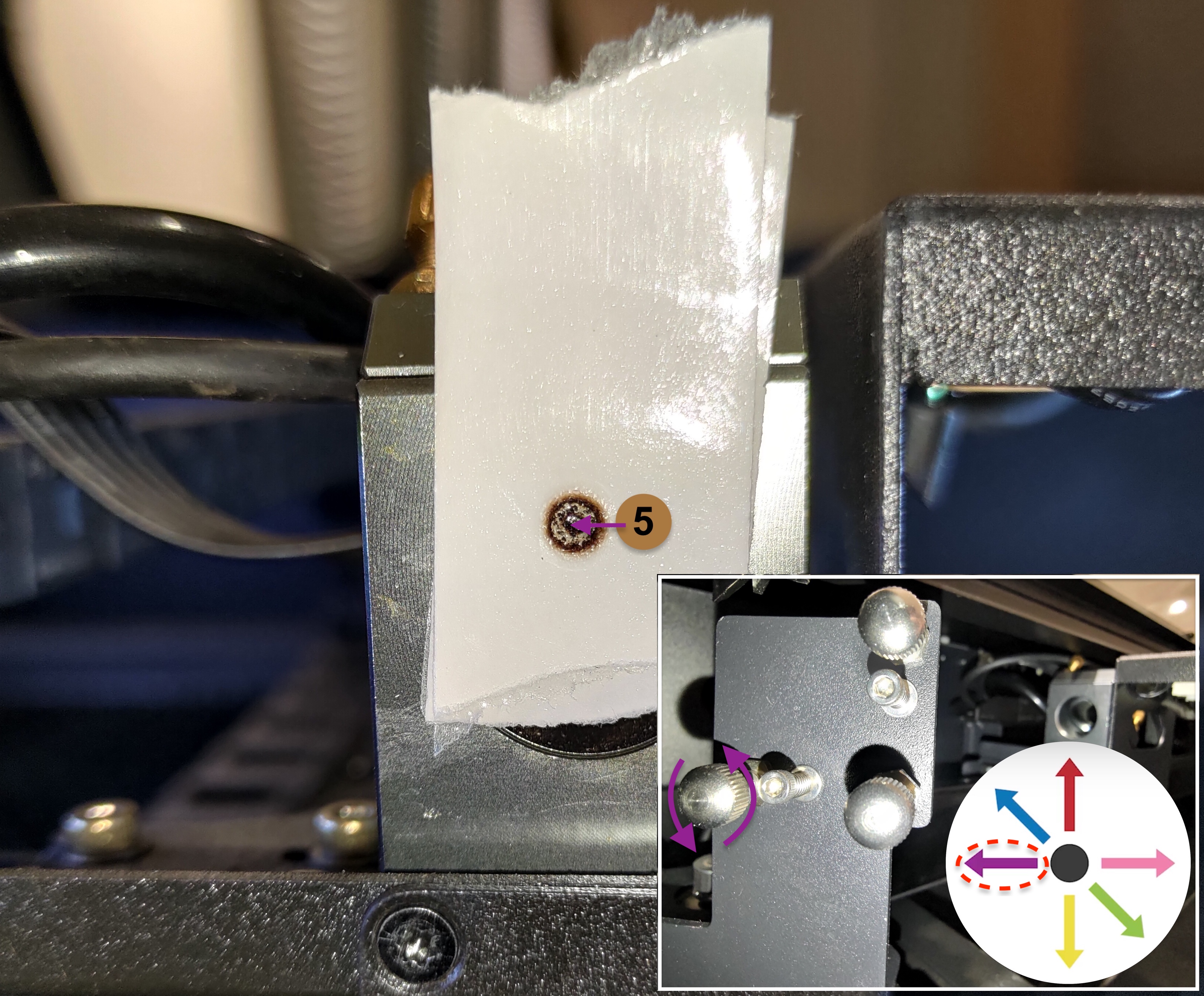
For #5:
The red laser dot needs to go left in order to overlap the first dot.
The bottom-left screw will need to be rotated counter-clockwise.
Please refer to the photo below.
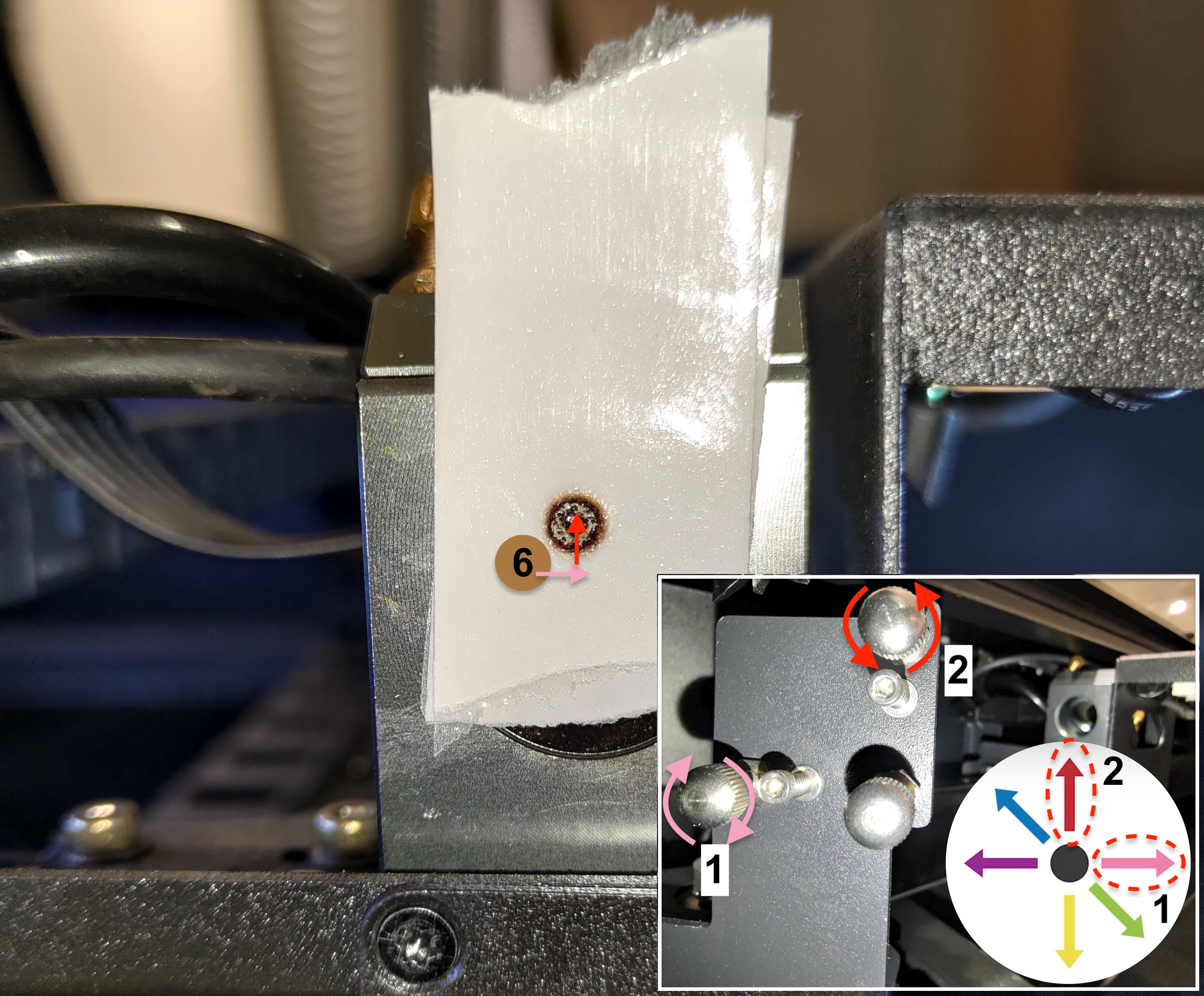
For #6:
The red laser dot needs to go right first and then go up in order to overlap the first dot.
The bottom-left screw will need to be rotated clockwise to make the dot go right.
The top-right screw will need to be rotated counter-clockwise to make the dot go up.
Please refer to the photo below.
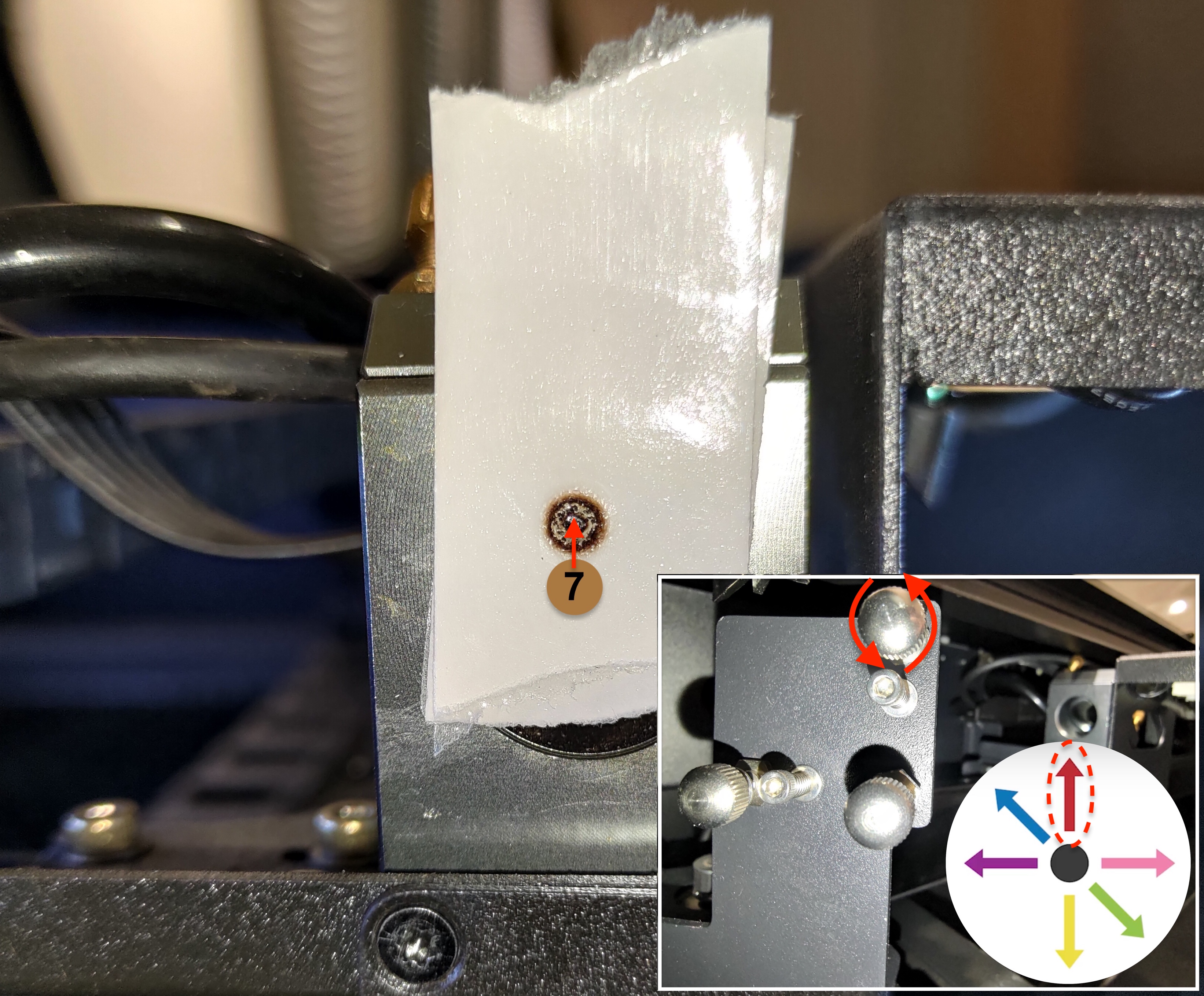
For #7:
The red laser dot needs to go straight up in order to overlap the first dot.
The top-right screw will need to be rotated counter-clockwise. Please refer to the photo below.
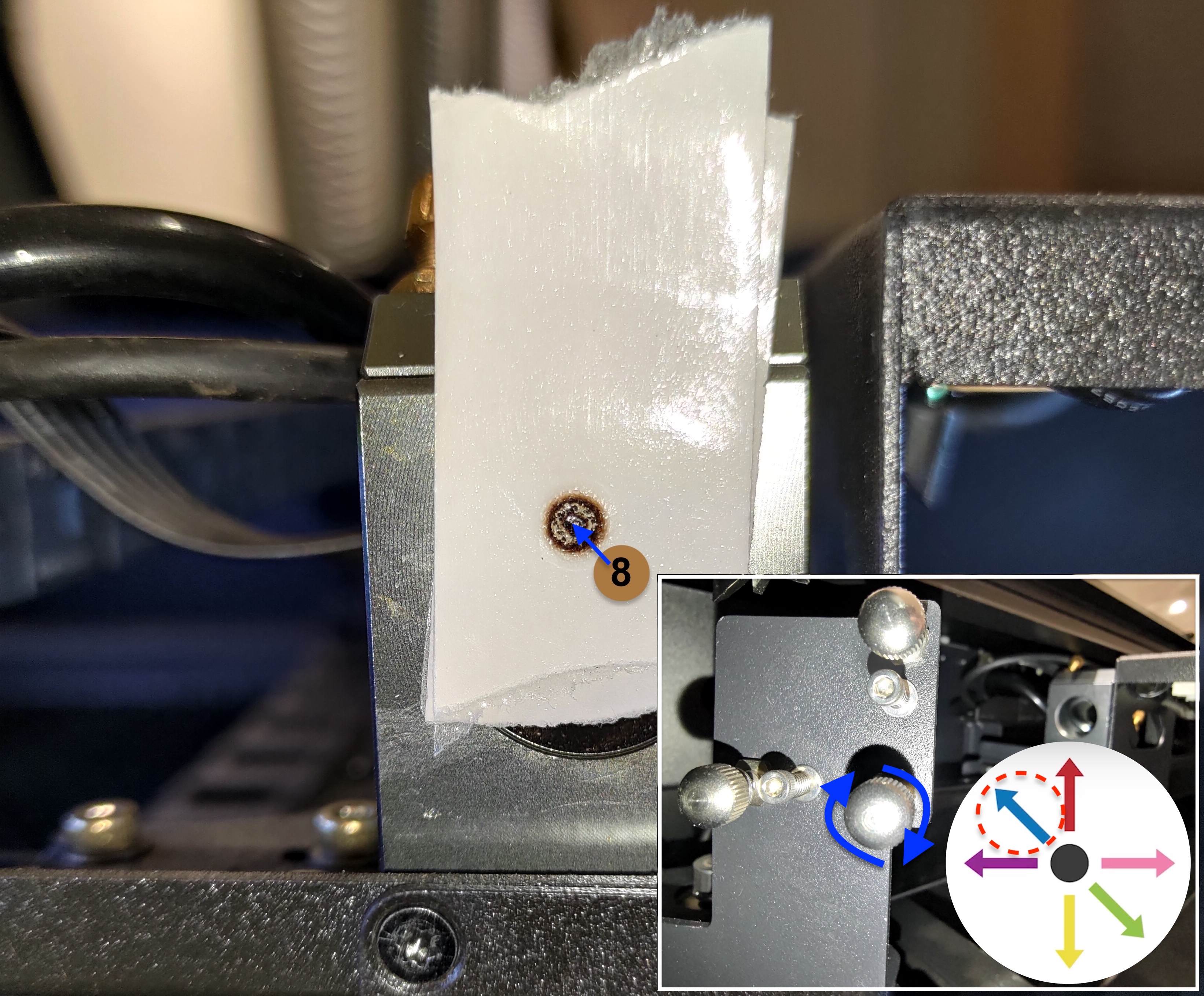
For #8:
The red laser dot needs to go up to the left in order to overlap the first dot
The bottom-right screw will need to be rotated clockwise. Please refer to the photo below.
-
Please tighten the nut after adjusting the screw by turning it clockwise.
|
Step 10
This step will teach you to check the beam's vertical entering position on the 3rd mirror entrance with an OPA tool.
-
Please use the link to download the file and use a 3mm transparent acrylic to engrave and cut.
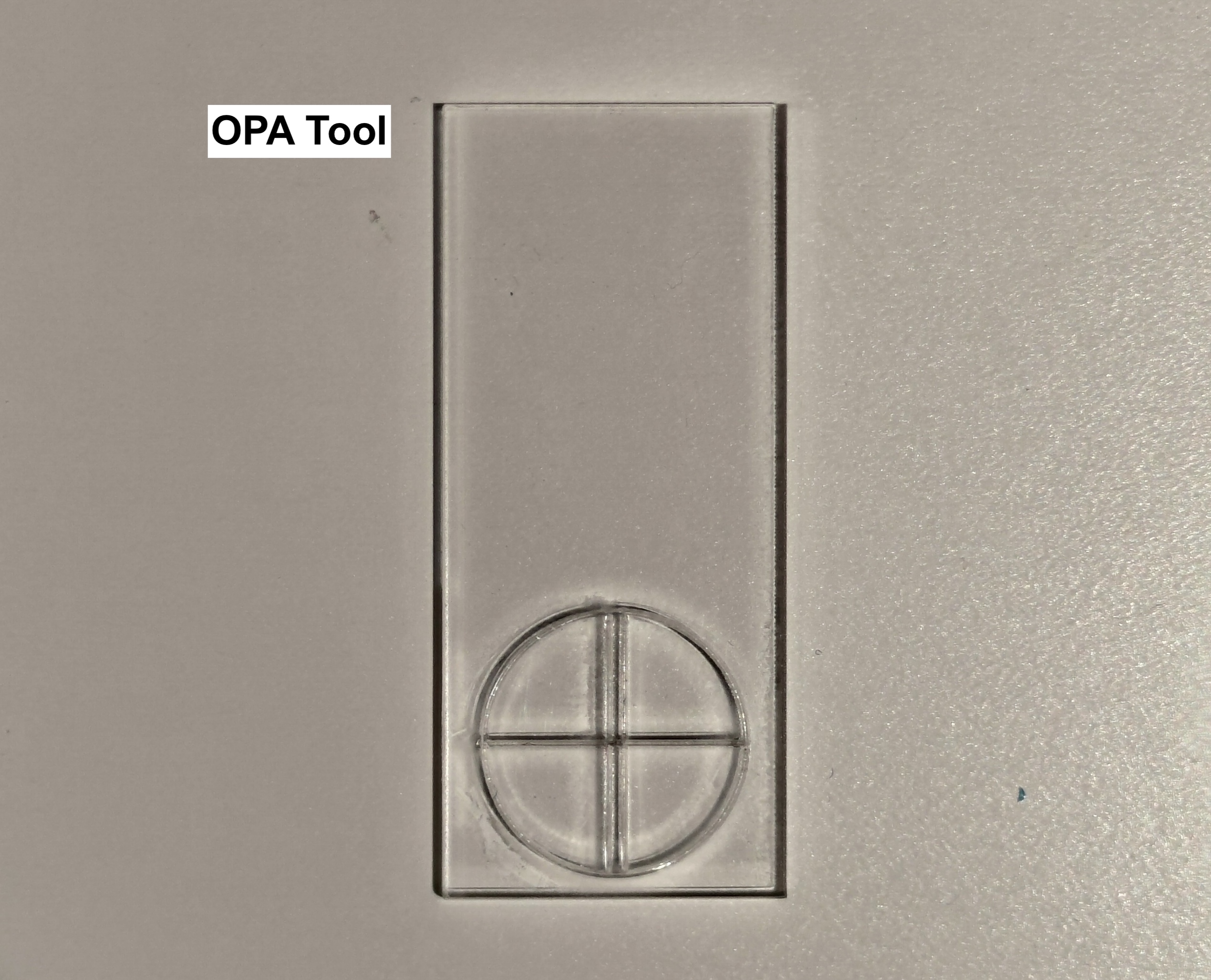
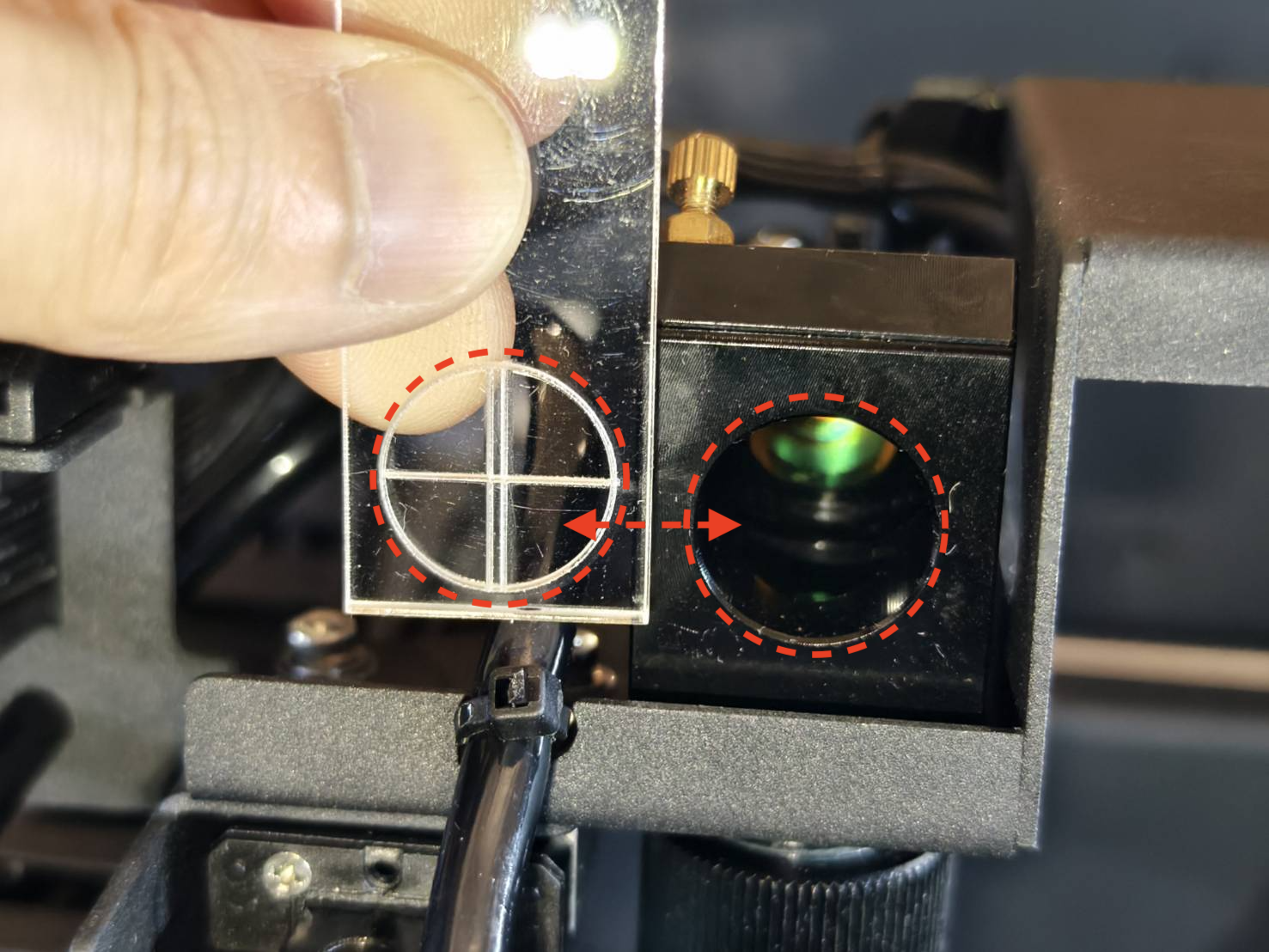
- The tool's circle will match the entrance as in the photo below.
|
-
If your machine can't cut through any area of the bed, you have to make a temporary tool.
Please use a piece of transparent tape and fold it to enclose the sticky part.
Draw two lines as in the photos below.
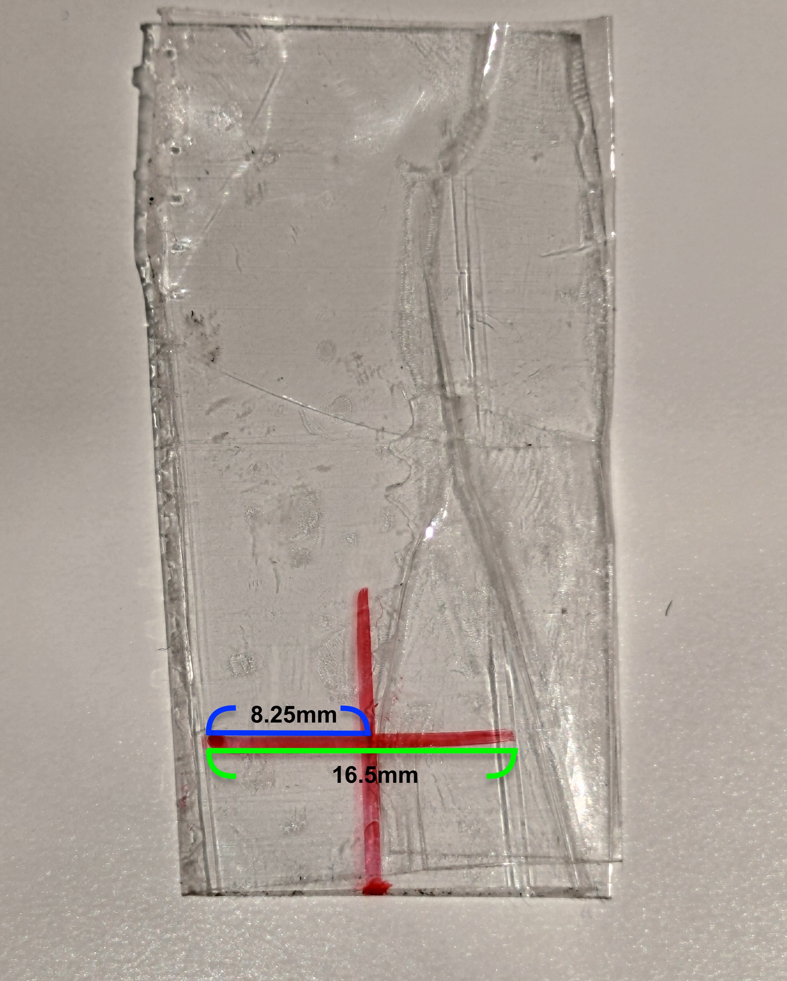 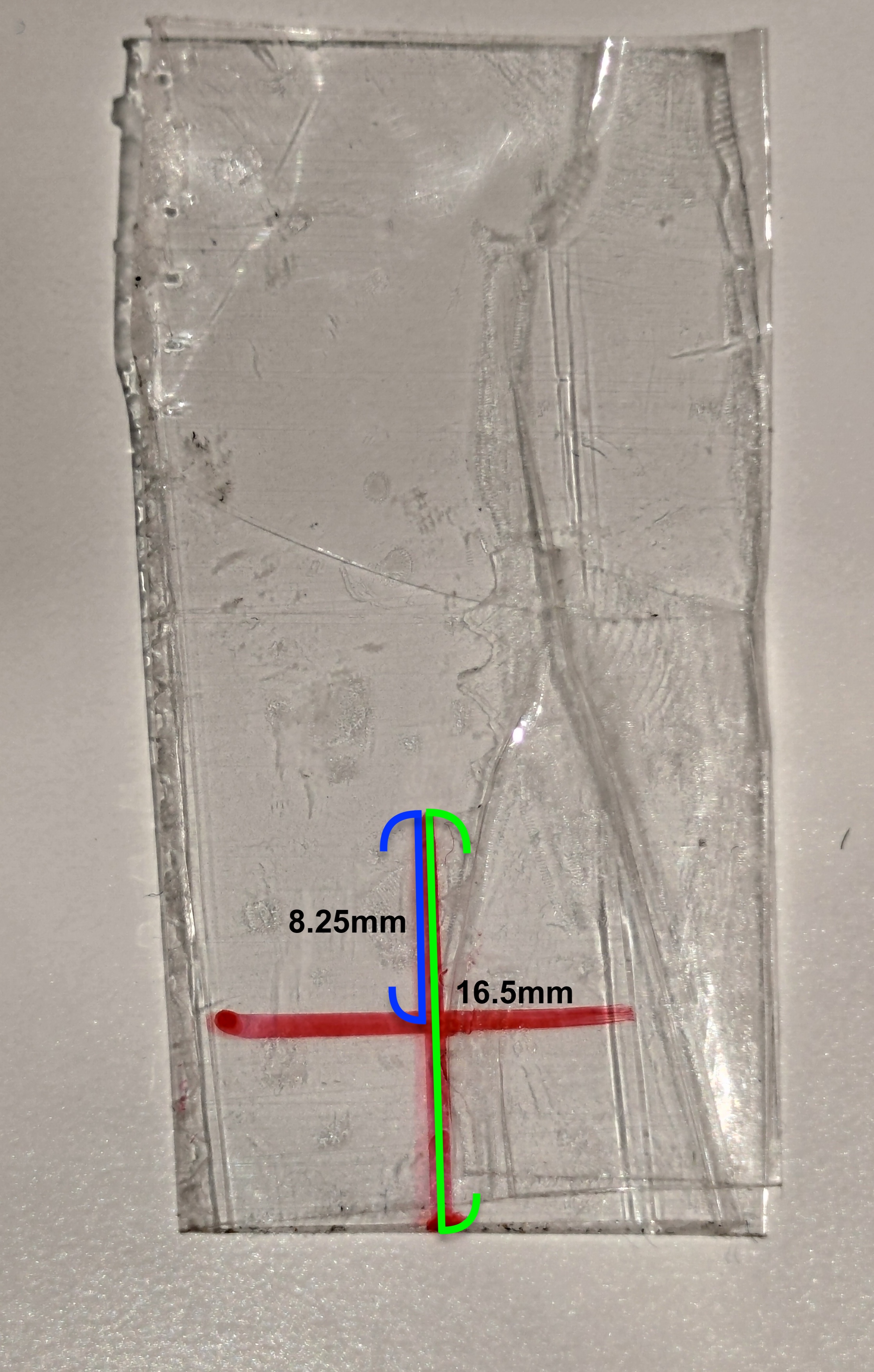
- The center of the lines on the tape will be the center of the round entrance.
(Suggest marking two marks as the red points in the photo below to align the lines on the tape.)
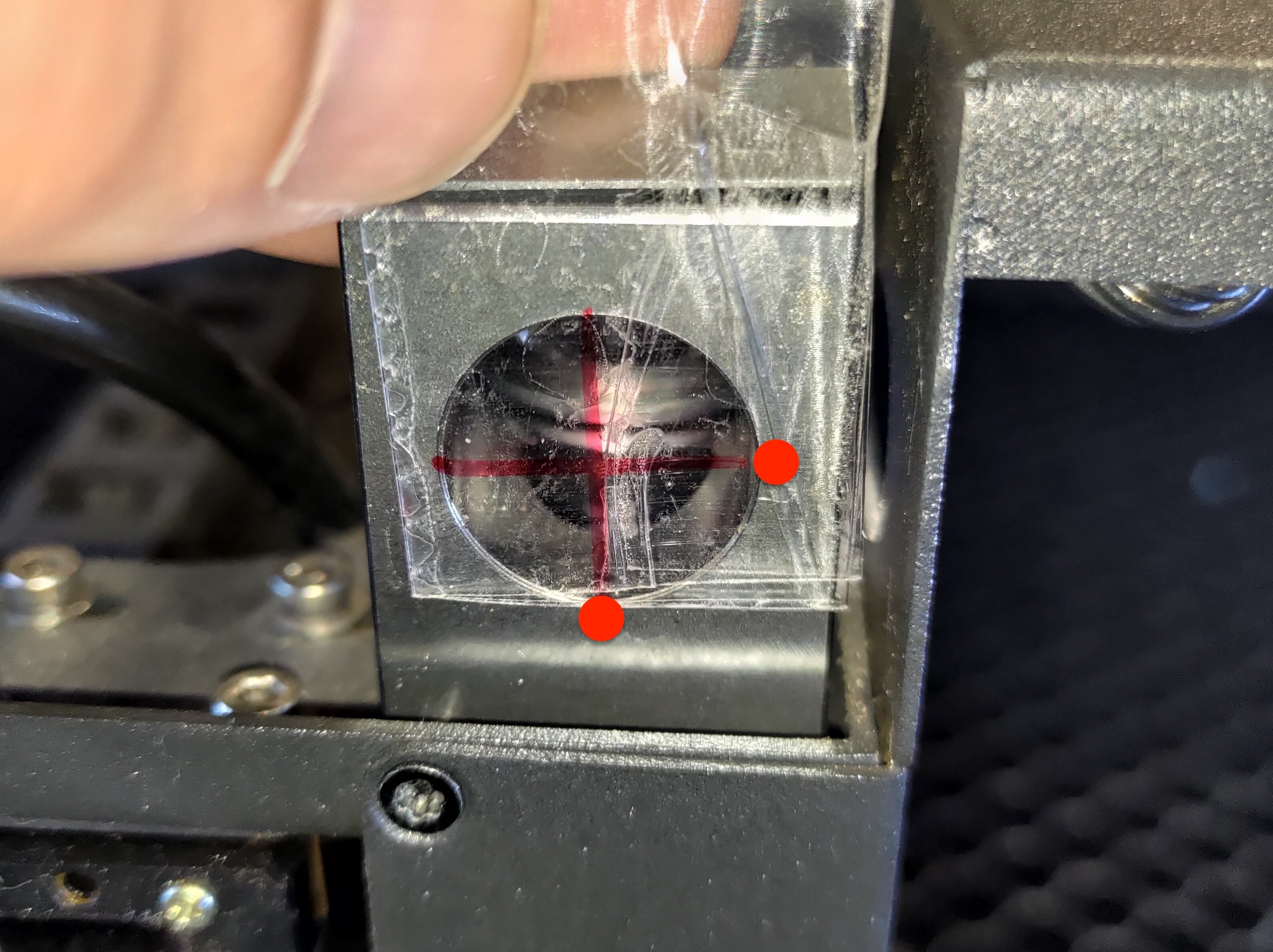
|
- Once you have the tool, move the laser head to the center.
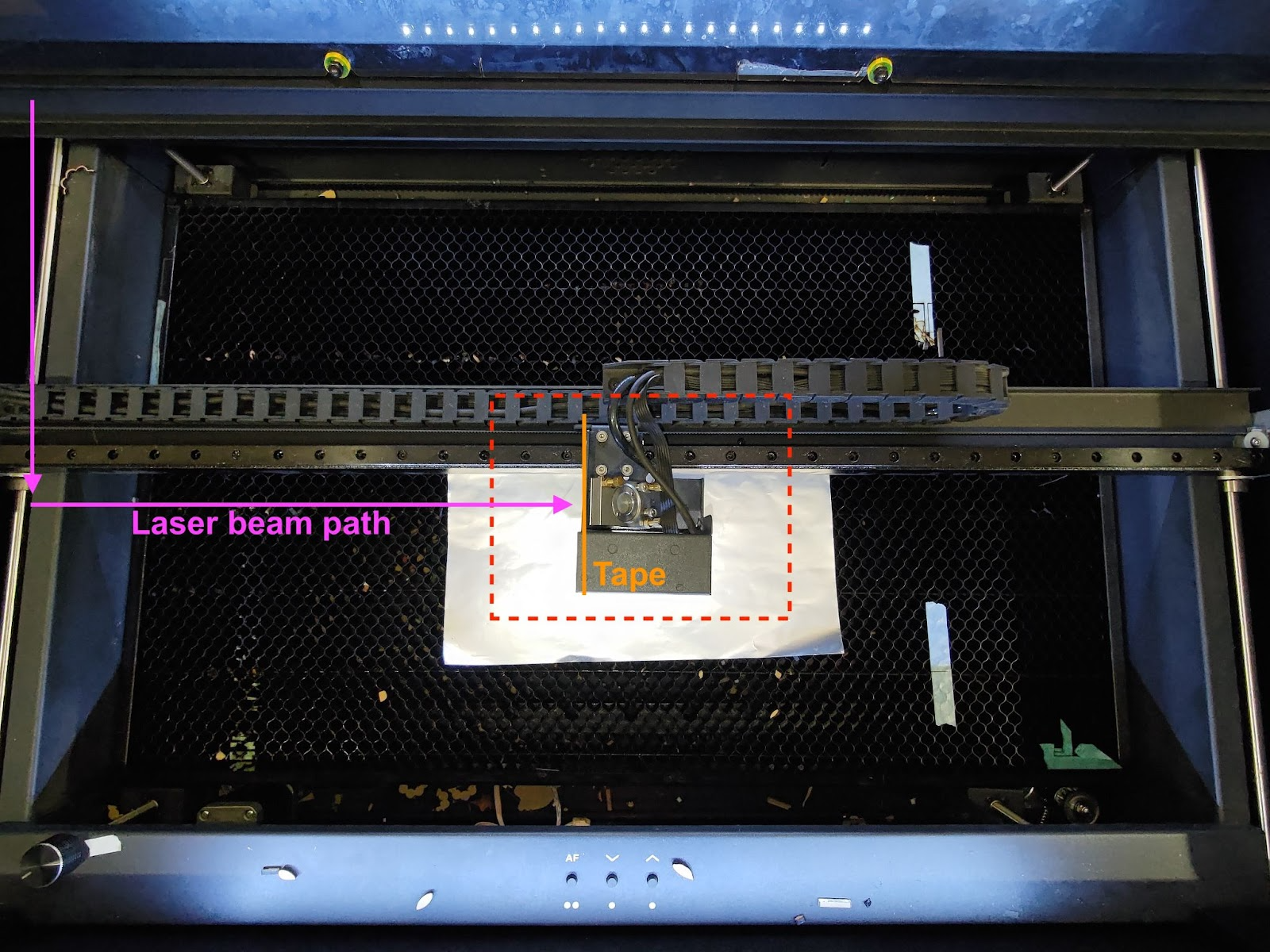
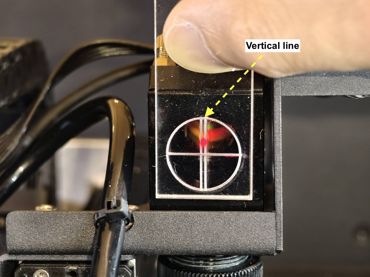
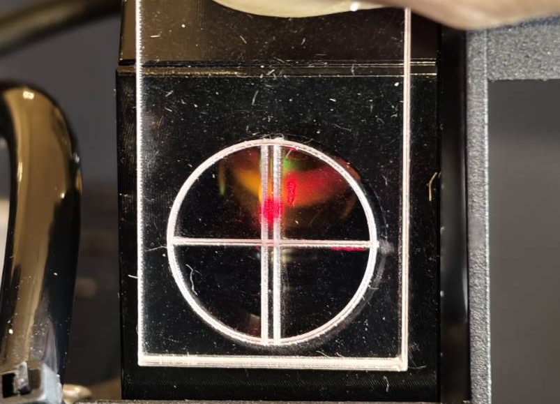
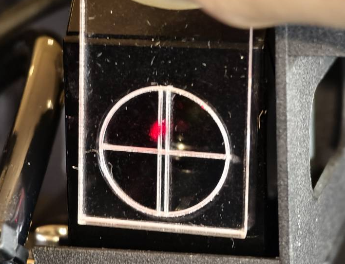
- Check the vertical line with the tool.
Align the tool's circle or points with the entrance and check the red laser dot's position.
Acrylic
|
|
|
|
Good Example
|
Bad Example
|
|
|
|
|
Determine your result and the next action to take:
Step 10.1
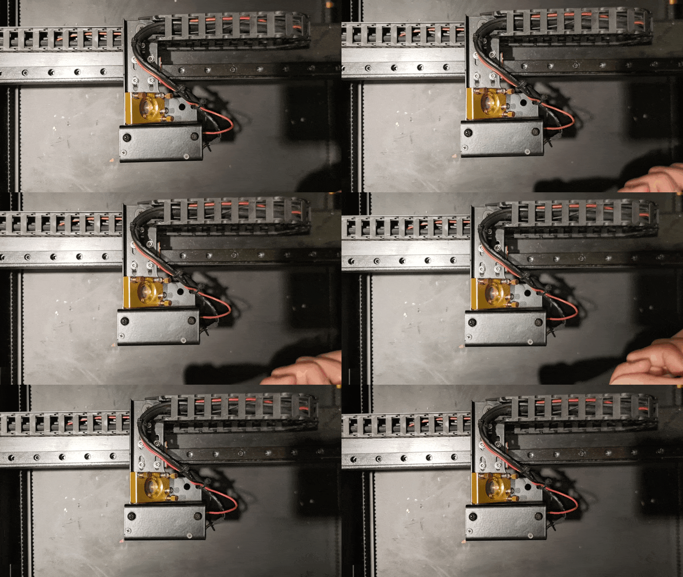
If your beam's vertical path is not in the center of the tool, you can adjust the laser head to improve it.
-
Slightly loosen these 4 screws, do not remove or make them too loose.
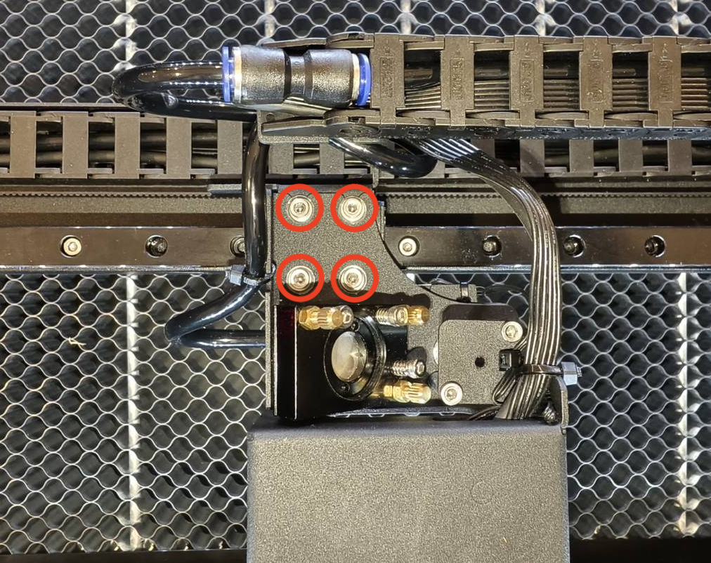
-
After loosening the screws, the head can now be pushed in or pushed out.
- Push out:
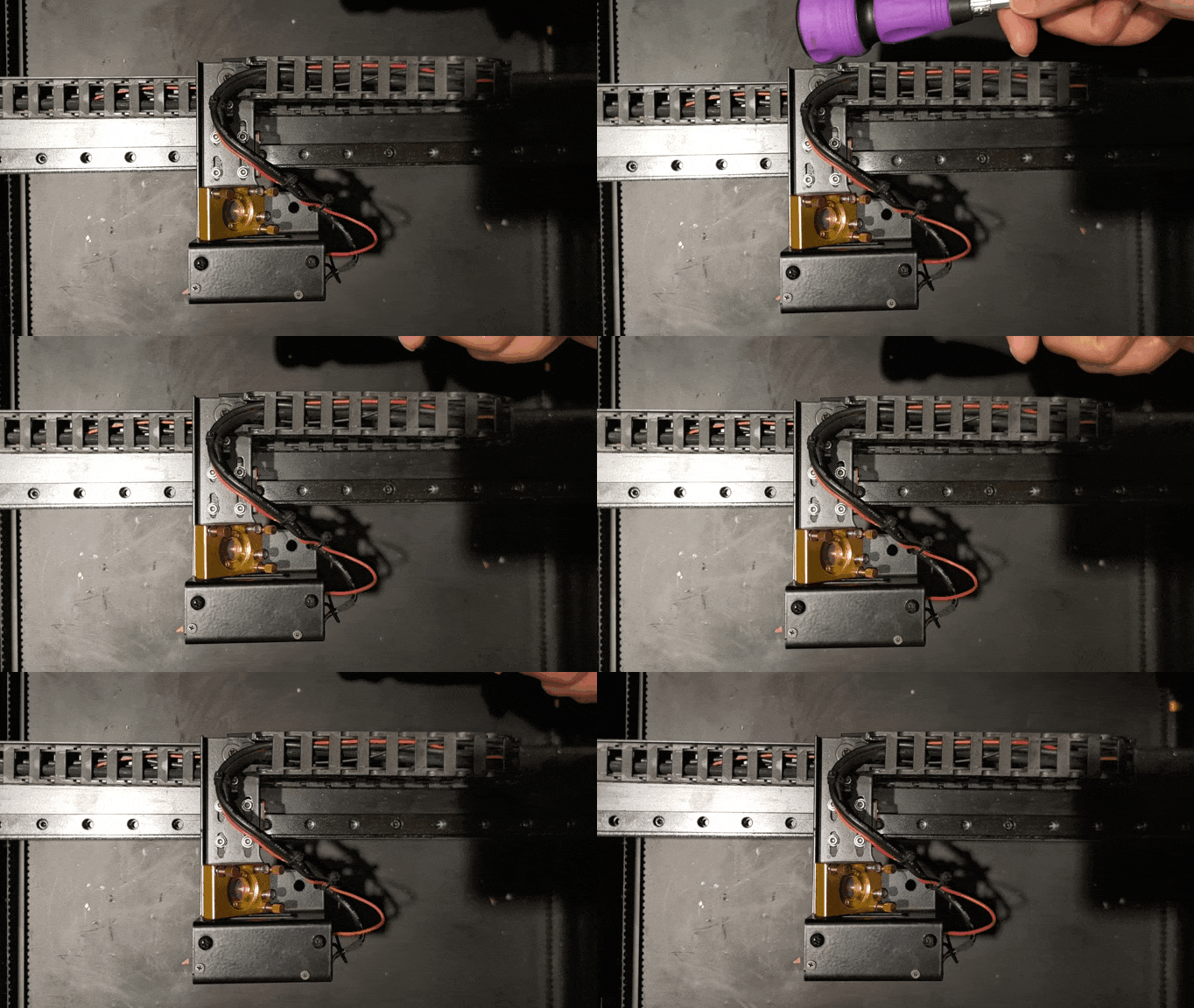
- Push in:
-
After moving the head, please screw back the screws.
-
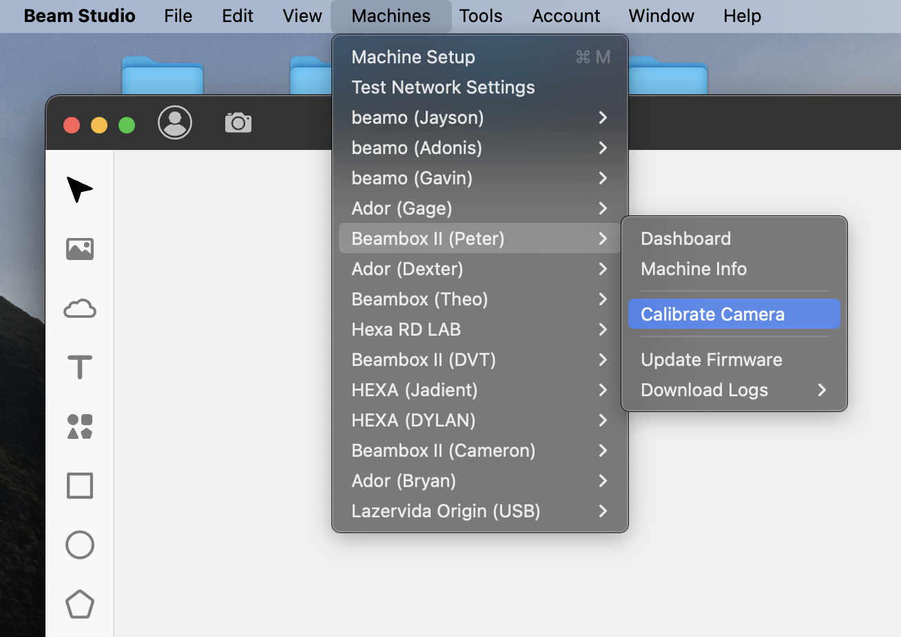
Please perform camera calibration in Beam Studio.
(This can be done as the last step after all the optical path alignment is finished.)
|
Step 11
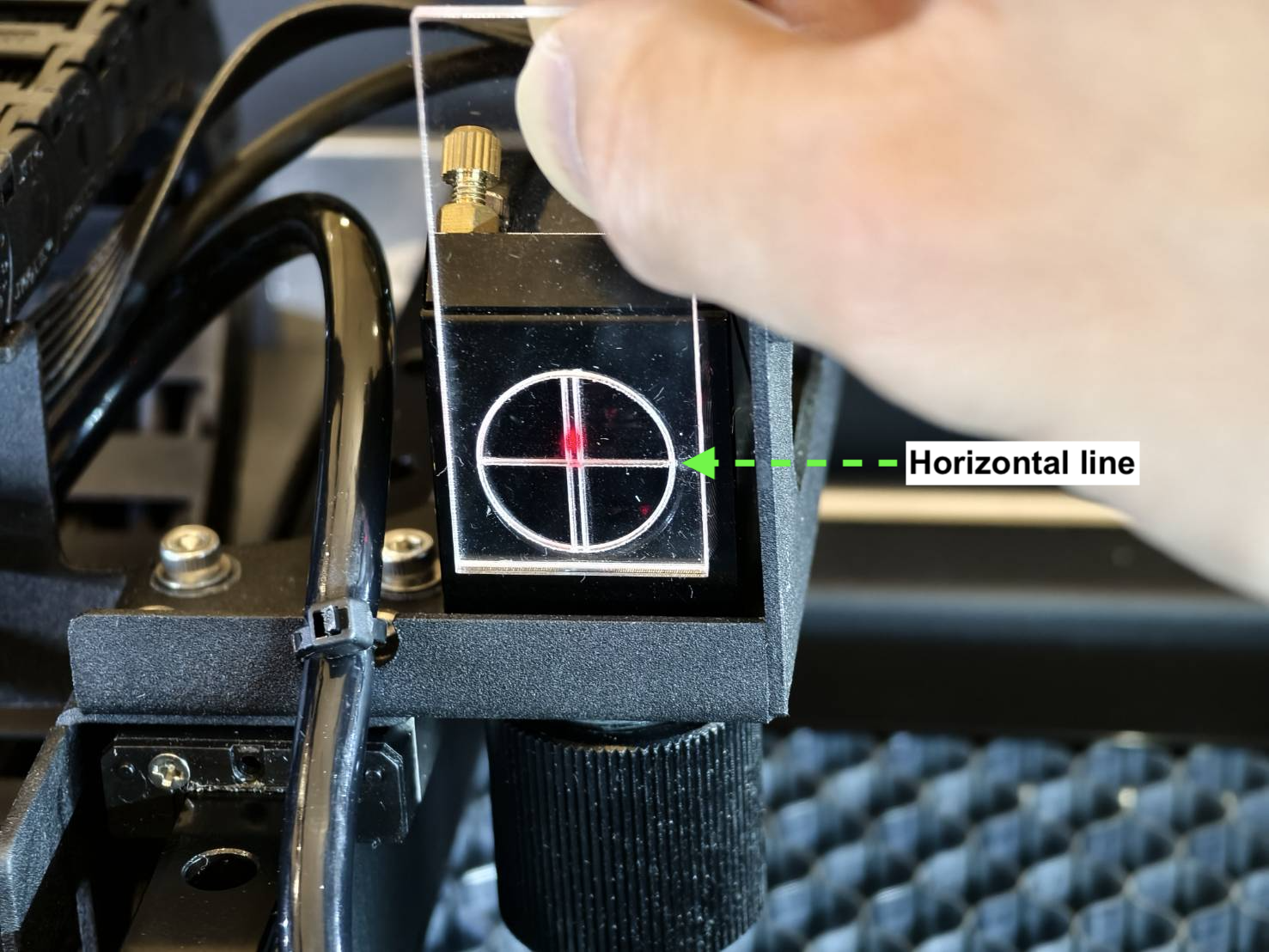
After the vertical check, we will check the horizontal position on the 3rd mirror entrance.
- Move the laser head to the center.
- Check the horizontal line with the tool.
Align the tool's circle or points with the entrance and check the red laser dot's position.
Acrylic
|
|
|
|
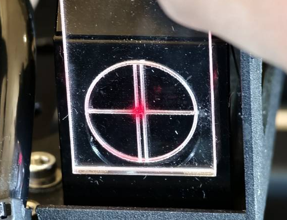
Good - Center
|
Acceptable - Above
|
Bad - Below
|
|
|
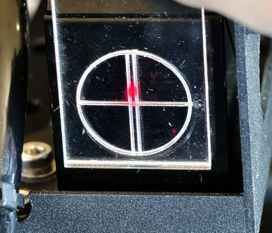
|
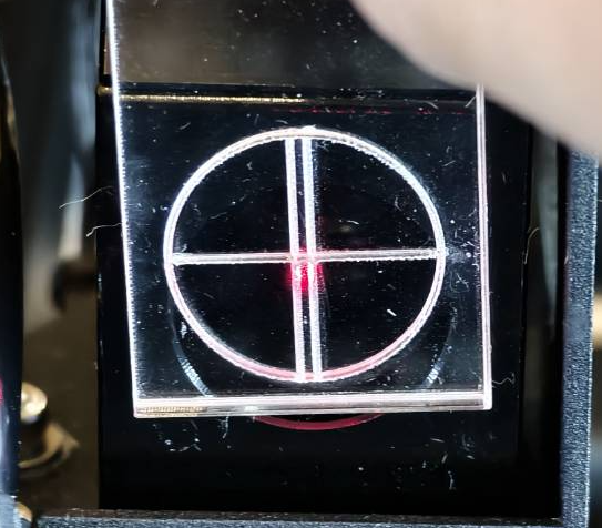
|
|
Determine your result and the next action to take:
- Good or acceptable result >> Step 12
|
-
Bad result >> Contact Customer Service
-
Possible cause:
- The laser beam's angle is off too much and it has to be raised up or replaced.
|
Step 12
We will now check the path from the 3rd mirror to the nozzle tip, which indicates the Z-axis (vertical) beam path at the center of the bed.
- Move the laser head to the center of the bed and place a piece of paper underneath the nozzle tip.
Raise or lower the bed to have a distance of around 5mm to 10mm between the paper and nozzle tip.
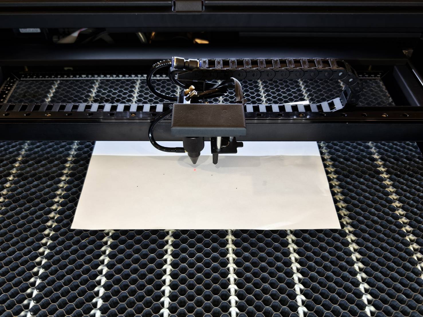
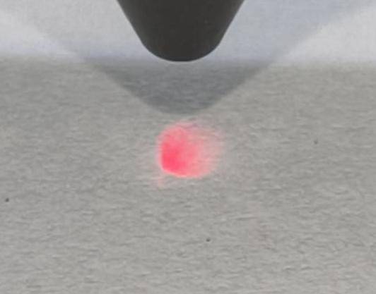
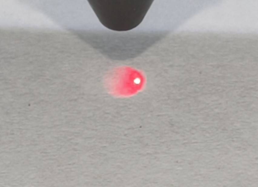
- Check if a focused red laser dot or red light is seen as in the photo below.
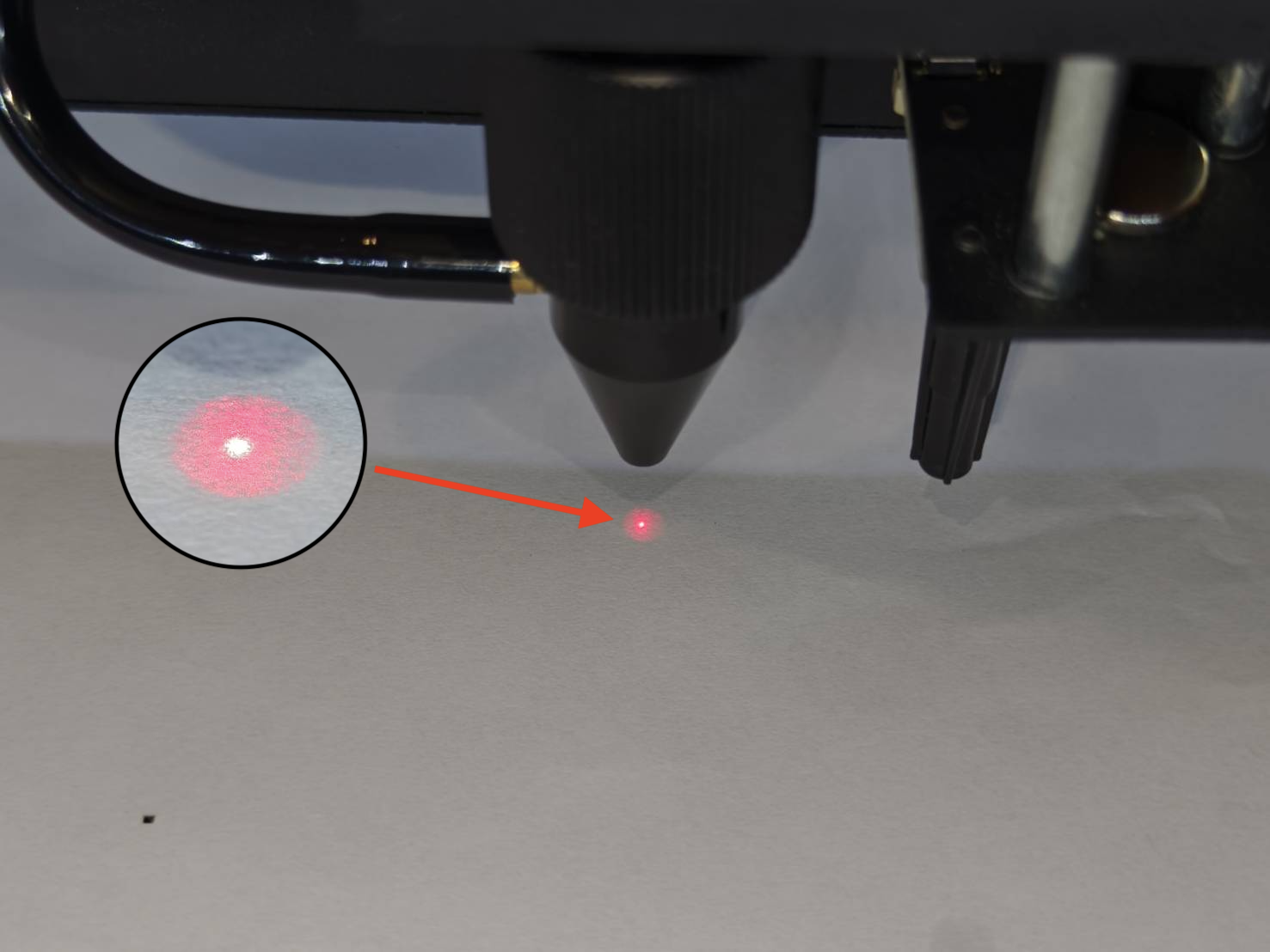
| Good Result - Cetner |
Bad Result - No dot |
Bad Result - Not Center |
 |
 |
 |
|
Determine your result and the next action to take:
Step 12.1
If a focused dot is not coming out from the nozzle or no dot is seen, your Z-axis path is misaligned and has to be adjusted. The goal here is to move the focused dot to the center.
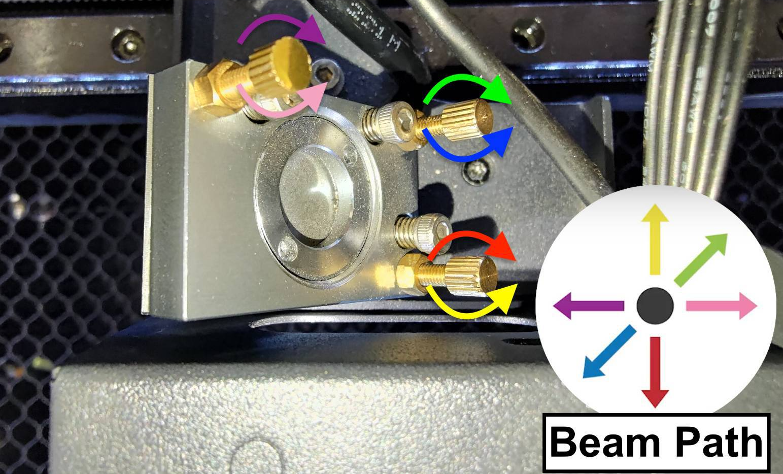
- This step will teach you how to align the vertical path from the 3rd mirror to the bed by adjusting the screws on the 3rd mirror.
There are three screws on the 3rd mirror, and rotating them clockwise or counter-clockwise will change the vertical beam path meaning the position of the little dot on the tape will change.
-
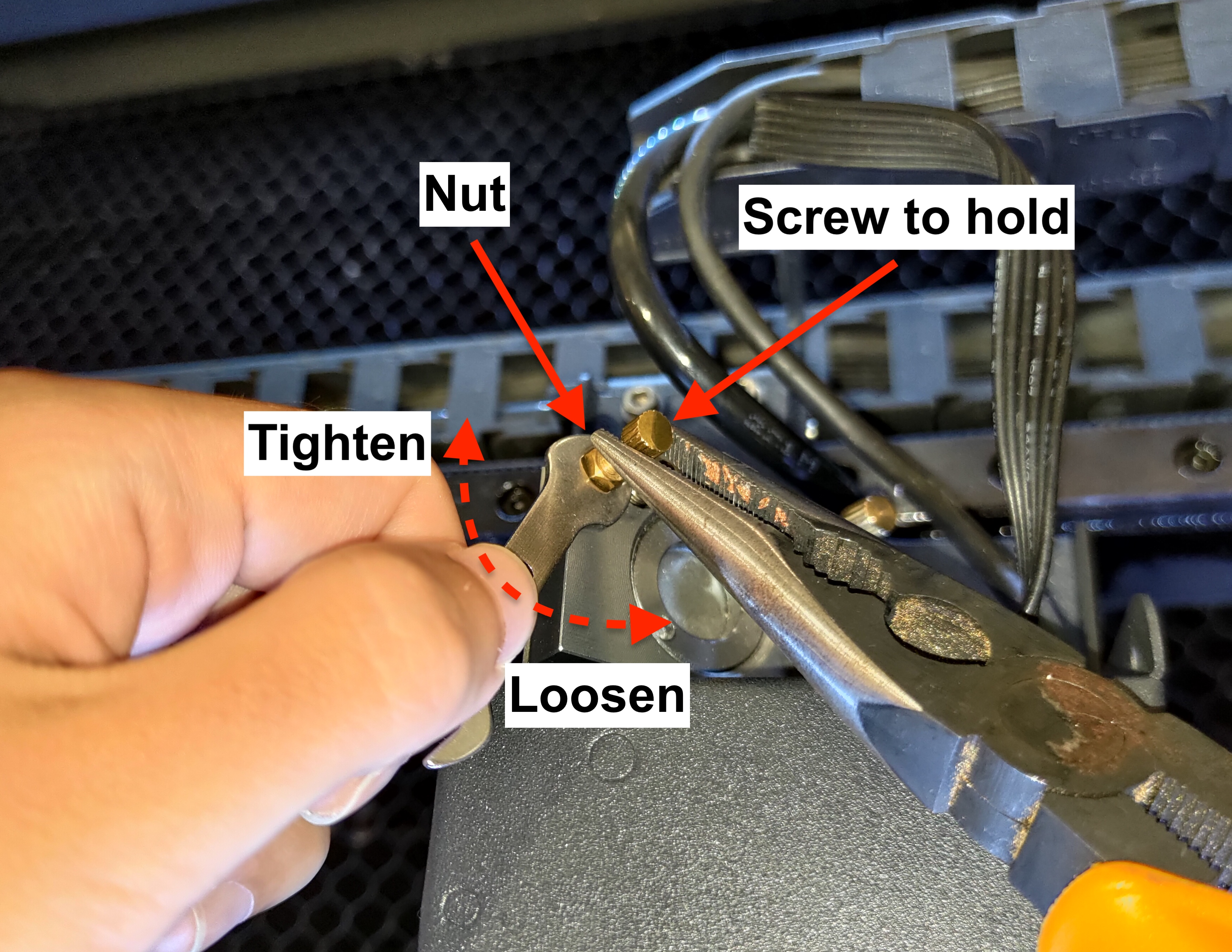
Please learn how to loosen the nut properly.
Use the pliers to hold the screw, then loosen the nut with the double-head wrench by turning it counter-clockwise.
|
- How do we determine the position of the laser dot?
If the focused dot is missing, you can see the red light that the stronger area indicates the position of your dot.
| Example |
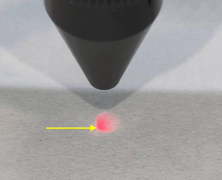
- The light is stronger, as pointed out in the photo, indicating the dot should be at the bottom to the left position.
|
 |
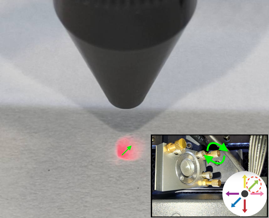
- In order to move the dot to the center, the dot has to go up and right, so rotating the top-right screw clockwise will be suggested.
|
 |
| Demonstration |
|
|
-
Please tighten the nut after adjusting the screw by turning it clockwise.
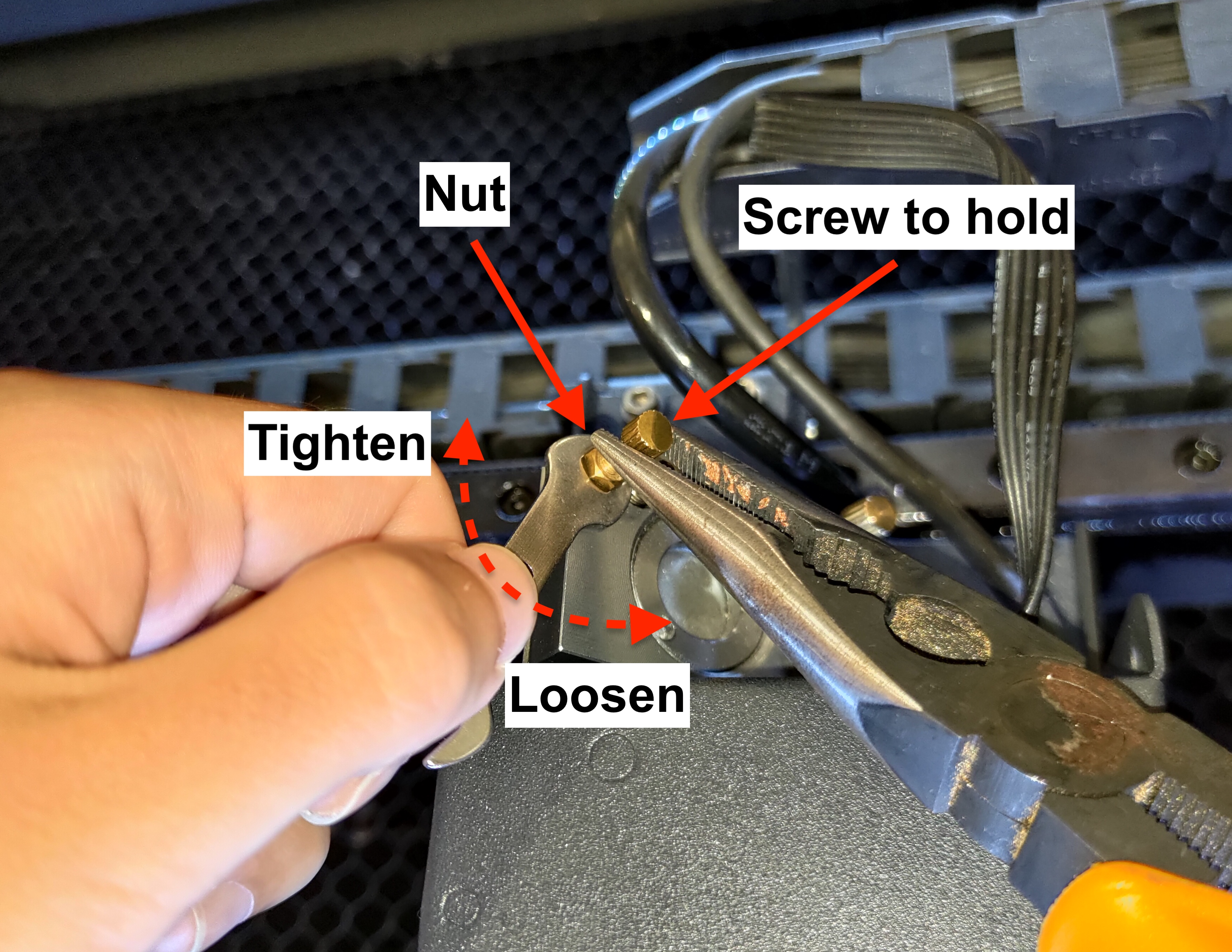
|
Determine your result and the next action to take:
- The adjustment is done with no problem >> Step 13
|
-
No matter how I adjust, the dot is not shown or can't be centered >>
|
Step 13
We will now check the path from the 3rd mirror to the nozzle tip at the bottom-right corner of the bed.
- Move the laser head to the bottom-right corner of the bed and place a piece of paper underneath the nozzle tip.
Raise or lower the bed to have a distance of around 5mm to 10mm between the paper and nozzle tip.
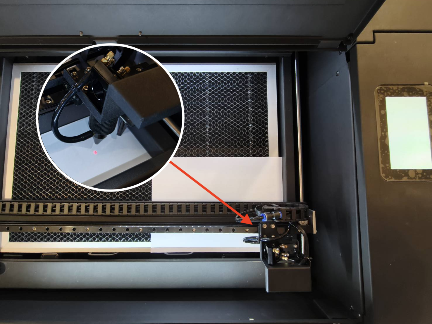
- Check if a focused red laser dot or red light is seen as in the photo below.
| Good Result - Cetner |
Bad Result - No dot |
Bad Result - Not Center |
|
|
|
|
Determine your result and the next action to take:
Step 13.1
If you don't have a focused dot coming out from the nozzle, it indicates your Z-axis path is misaligned and has to be adjusted.
The goal here is to move the focused dot to the center in the bottom right corner.
- This step will teach you how to align the vertical path from the 3rd mirror to the bed by adjusting the screws on the 3rd mirror.
There are three screws on the 3rd mirror, and rotating them clockwise or counter-clockwise will change the vertical beam path meaning the position of the little dot on the tape will change.
-
Please learn how to loosen the nut properly.
Use the pliers to hold the screw, then loosen the nut with the double-head wrench by turning it counter-clockwise.
|
- How to determine the position of the laser dot?
If the focused dot is missing, you can see the red light. The stronger aread indicates the position of your dot.
| Example |
- The light is stronger as pointed in the photo and it indicates the dot should be at the bottom to the left position.
|
|
- In order to move the dot to the center, the dot has to go up and right, so rotating the top-right screw clockwise will be suggested.
|
|
| Demonstration |
|
|
-
Please tighten the nut after adjusting the screw by turning it clockwise.
|
Determine your result and the next action to take:
- The adjustment is done with no problem >> Step 14
|
-
No matter how I adjust, the dot is not shown or can't be centered >>
- Back to Step 12.1 and make sure the dot is centered in the center of the bed.
- After adjusting, directly skip to Step 14.
|
Step 14
We will perform the final check using tapes and pulses to see the actual CO2 laser path starting from the center of the bed.
|
Step overview - Center
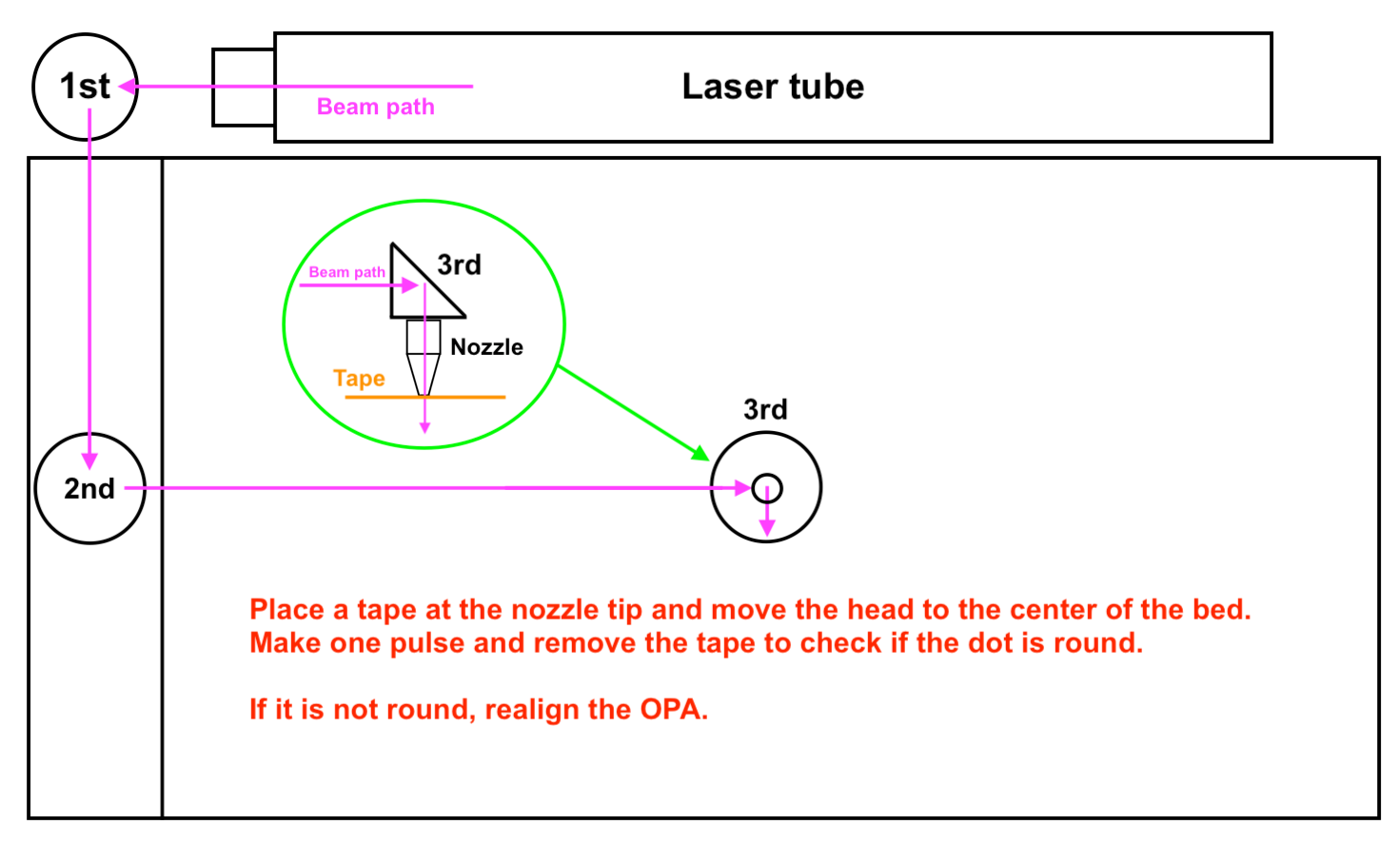
|
-
Place a one-layer tape on the nozzle tip, move the laser head to the center of the bed, close the door, and then make one pulse.
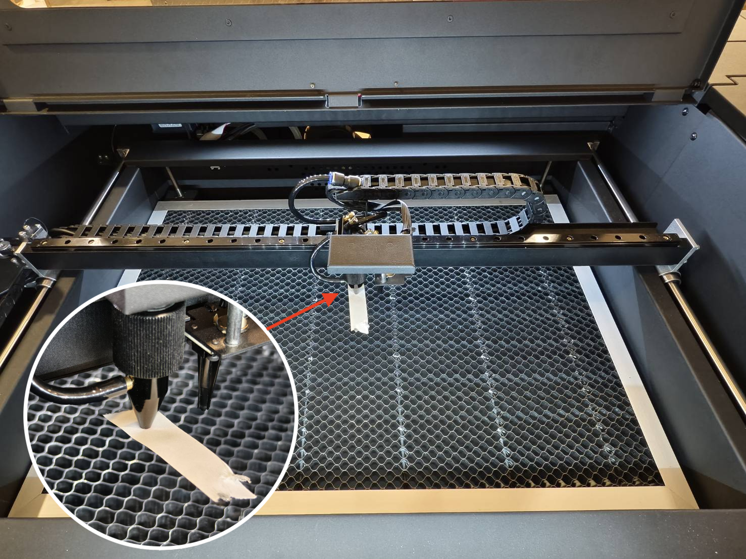
- Demonstration
|
-
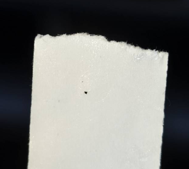
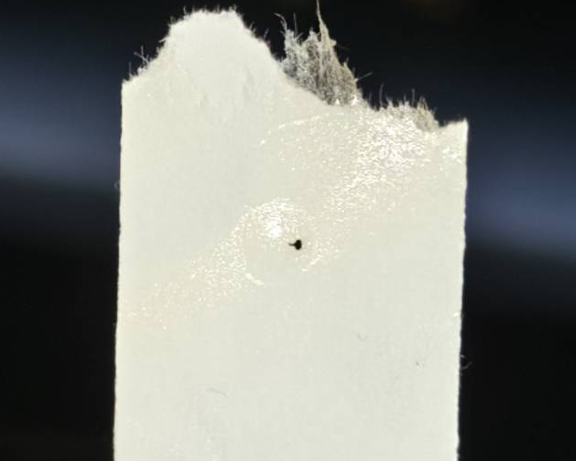
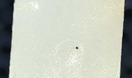
Remove the tape and check if the dot is round.
-
Good example - Center and Round:
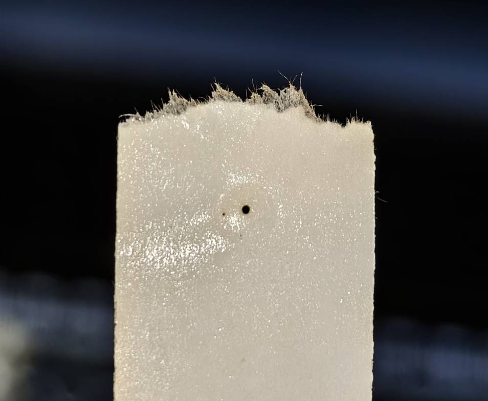
-
Acceptable example - Round but a little bit off from the center:
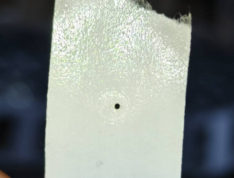
-
Bad examples - Not Round:
|
Determine your result and the next action to take:
- Good or acceptable result >> Step 15
|
Step 14.1
There is still a possibility that the red laser path and the actual CO2 laser path do not match 100%.
This means that even if a red dot is adjusted perfectly, the CO2 laser path may still be off.
Therefore, we have to use the traditional way to adjust the Z-axis path.
Workflow Demonstration:
-
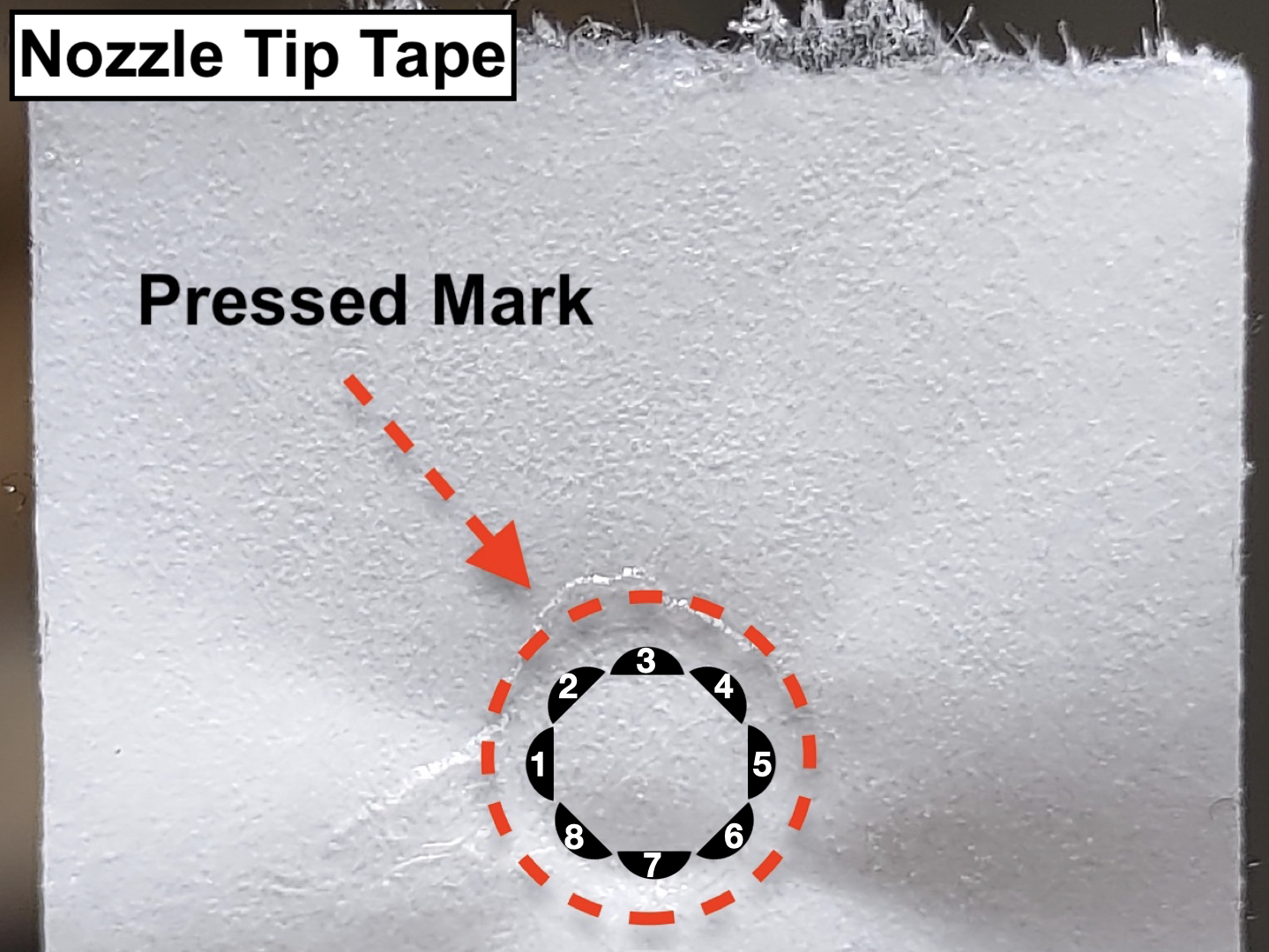
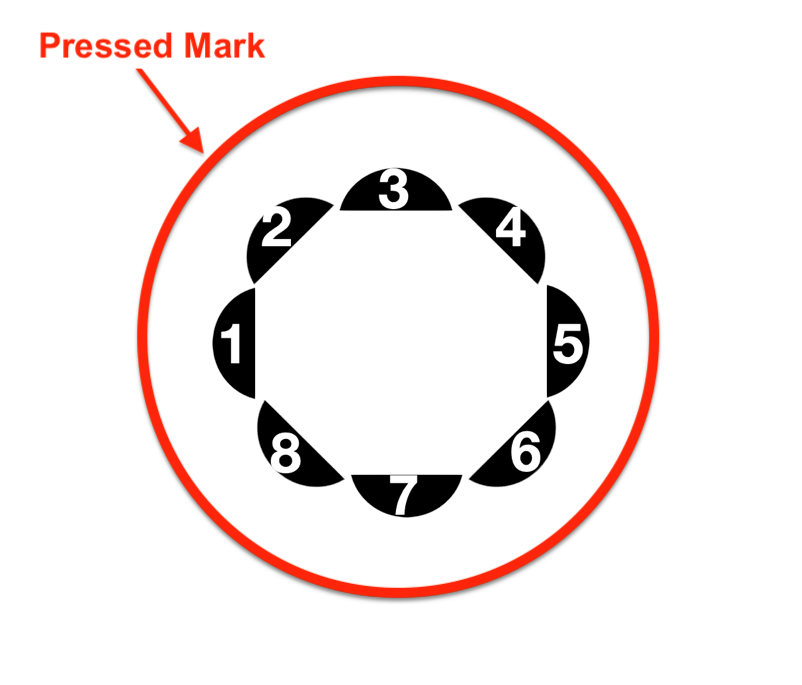
Determine the position of the vertical dot and target the screw and its direction of rotation. First, you will have to know the whole area to which the dot can move.
It is actually the same area as the nozzle tip. The pressed mark on the tape is the area.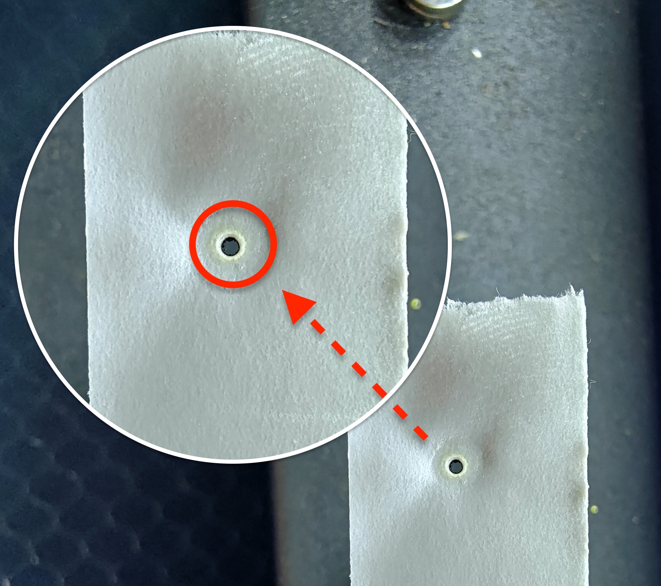
- Next, find the number that is similar to your vertical dot's position.
-
Schematic graph:
-
Please learn how to loosen the nut properly:
Use the pliers to hold the screw, then loosen the nut with the double-head wrench by turning it counter-clockwise.
|
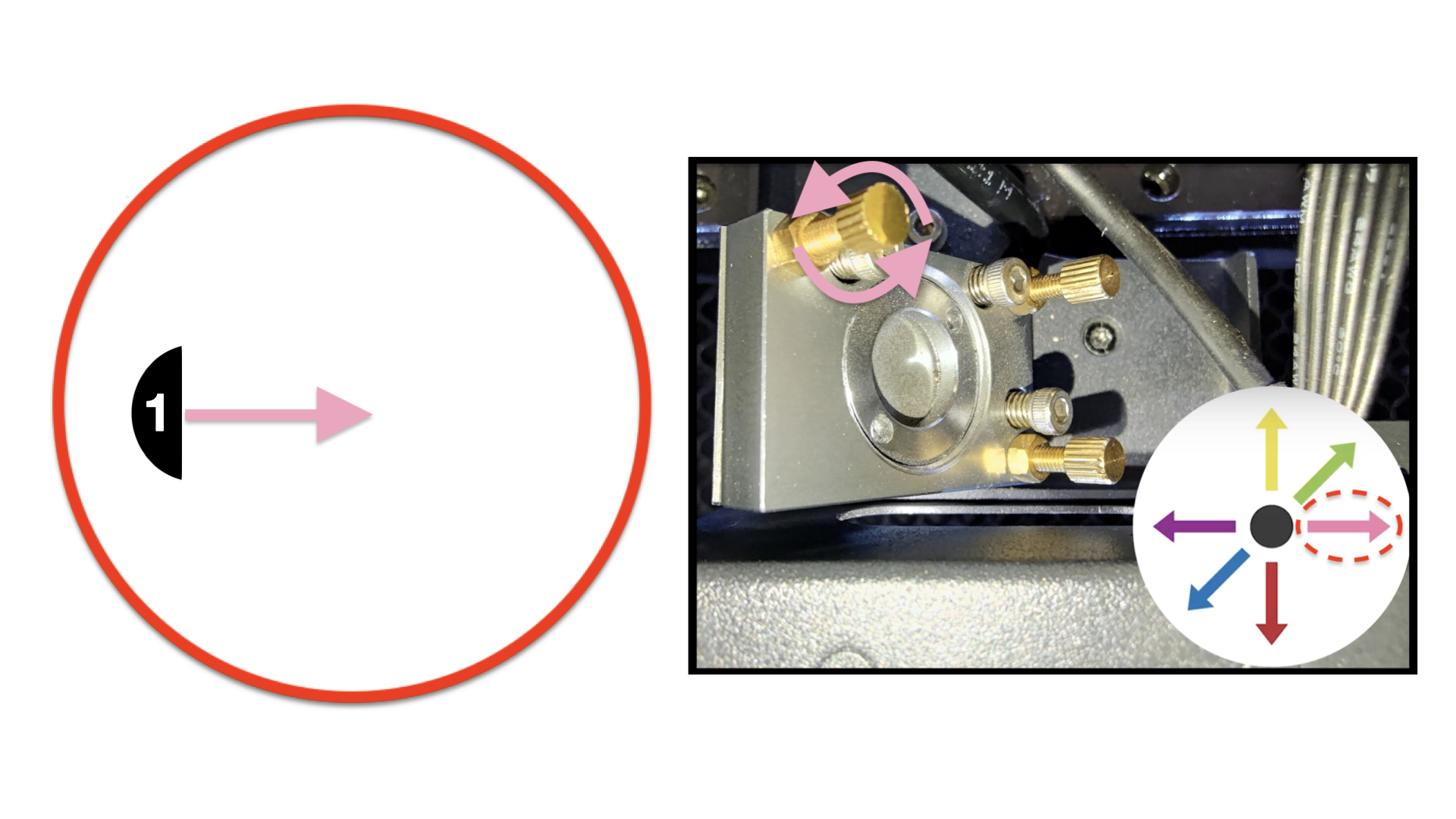
For #1:
The vertical dot needs to go right in order to be round and in the center.
When facing the front of the machine:
The top-left screw will need to be rotated counter-clockwise.
Please refer to the photo below.
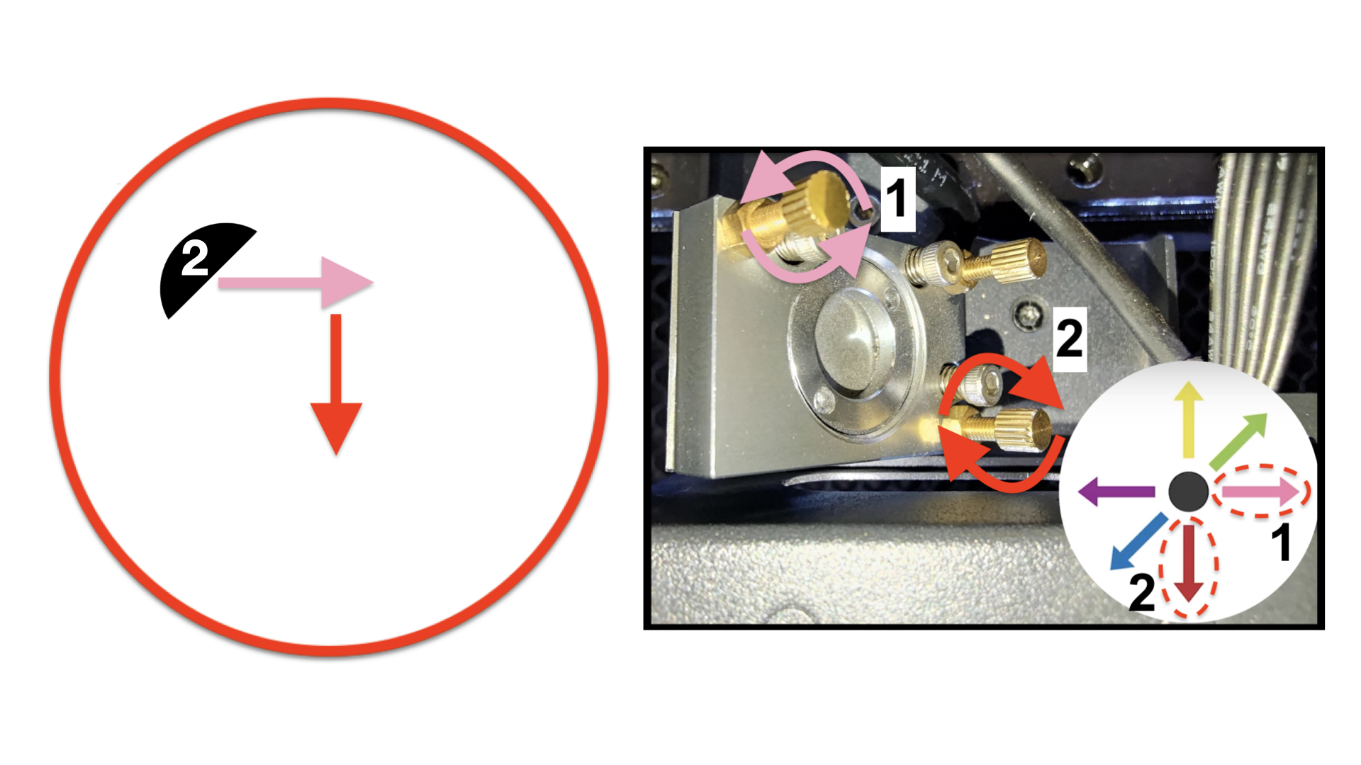
For #2:
The vertical dot needs to go down to the right in order to be round and in the center.
When facing the front of the machine:
The top-left screw will need to be rotated counter-clockwise in order to go right.
The bottom-right screw will need to be rotated clockwise in order to go down.
Please refer to the photo below.
For #3:
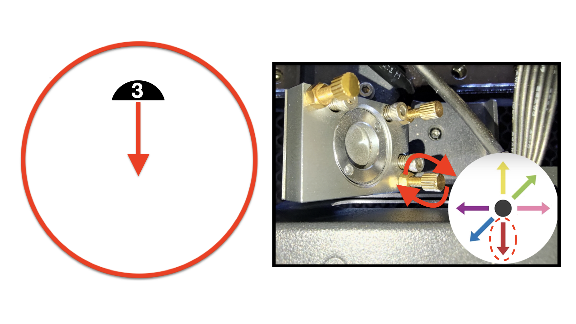
The vertical dot needs to go down in order to be round and in the center.
When facing the front of the machine:
The bottom-right screw will need to be rotated clockwise in order to go down.
Please refer to the photo below.
For #4:
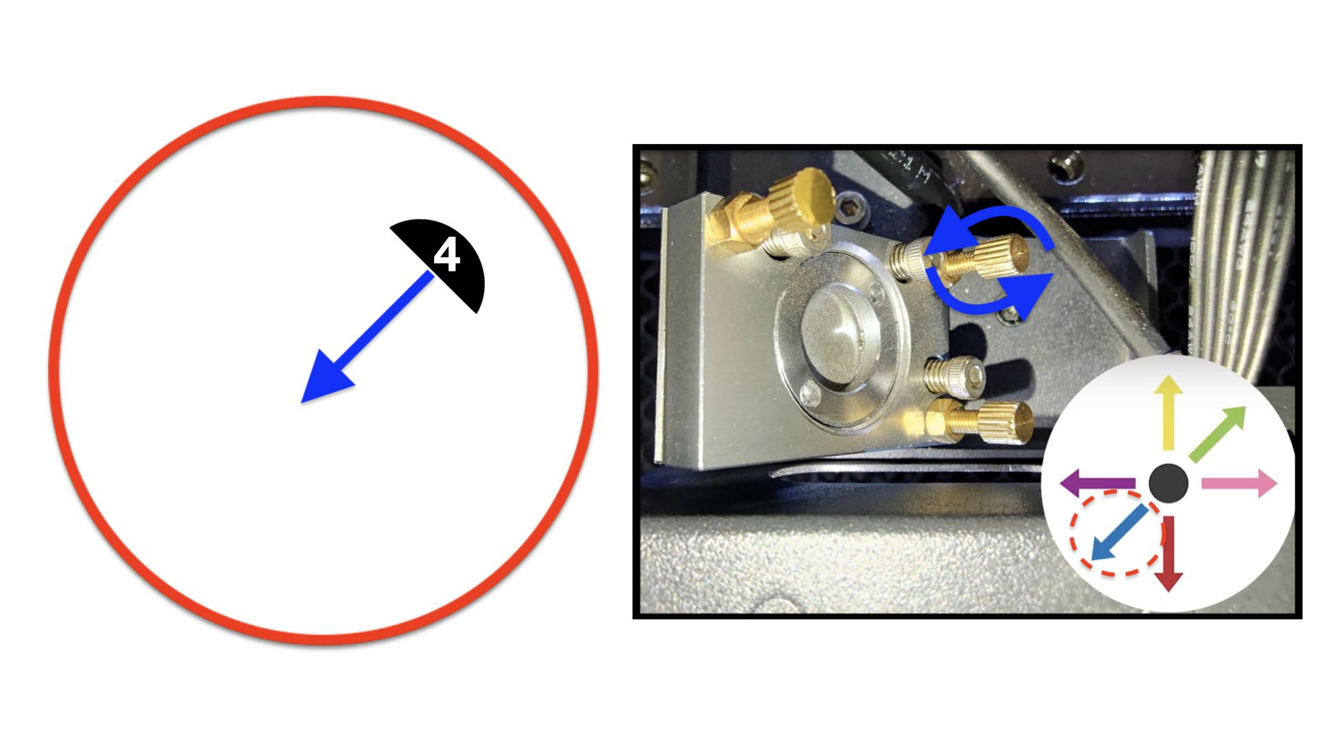
The vertical dot needs to go down to the left in order to be round and in the center.
When facing the front of the machine:
The top-right screw will need to be rotated counter-clockwise.
Please refer to the photo below.
For #5:
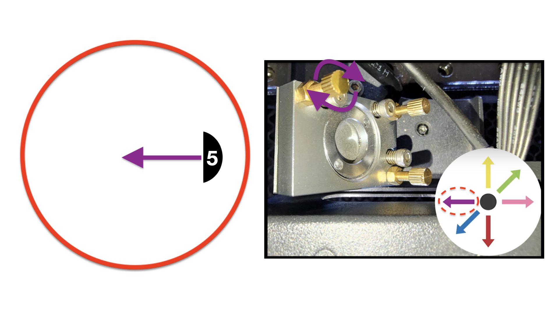
The vertical dot needs to go left in order to be round and in the center.
When facing the front of the machine:
The top-left screw will need to be rotated clockwise.
Please refer to the photo below.
For #6:
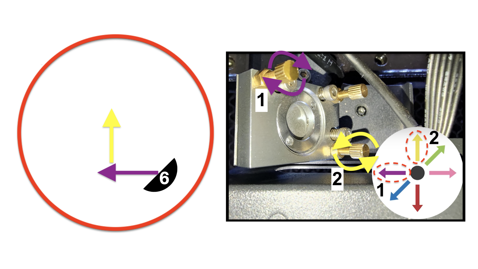
The vertical dot needs to go up to the left in order to be round and in the center.
When facing the front of the machine:
The top-left screw will need to be rotated clockwise in order to go left.
The bottom-right screw will need to be rotated counter-clockwise in order to go up.
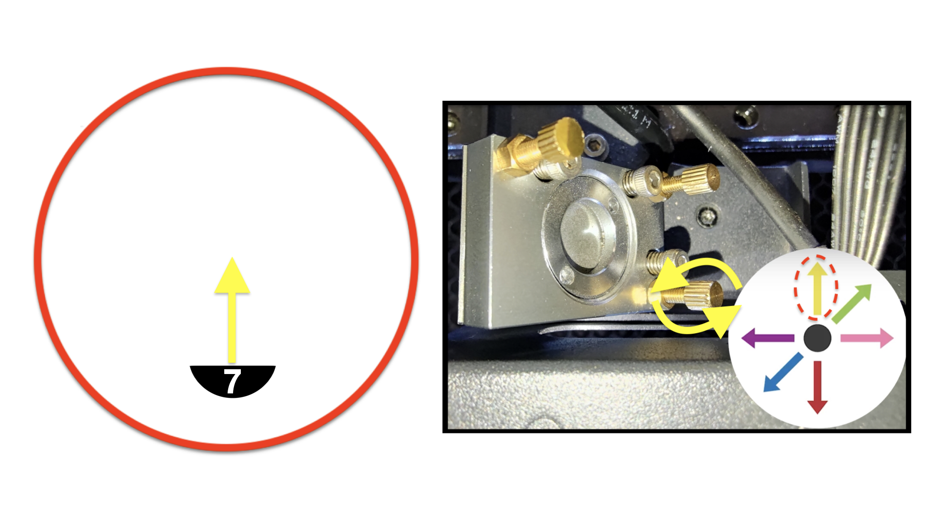
Please refer to the photo below.
For #7:
The vertical dot needs to go up in order to be round and in the center.
When facing the front of the machine:
The bottom-right screw will need to be rotated counter-clockwise in order to go up.
Please refer to the photo below.
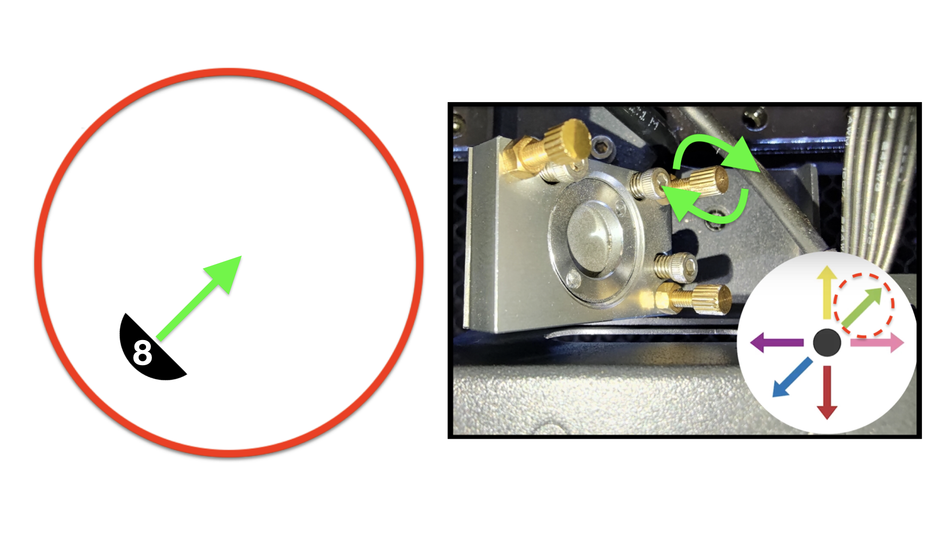
For #8:
The vertical dot needs to go up to the right in order to be round and in the center.
When facing the front of the machine:
The top-right screw will need to be rotated clockwise.
Please refer to the photo below.
|
- Once you finish adjusting the screw, you have to apply a new tape and make another pulse to see the dot's position.
-
Workflow Demonstration:
- If you have difficulty using this method, you can use the red dot to know the approximate location of the actual CO2 path and then make a pulse.
-
Please tighten the nut after adjusting the screw by turning it clockwise.
|
Step 15
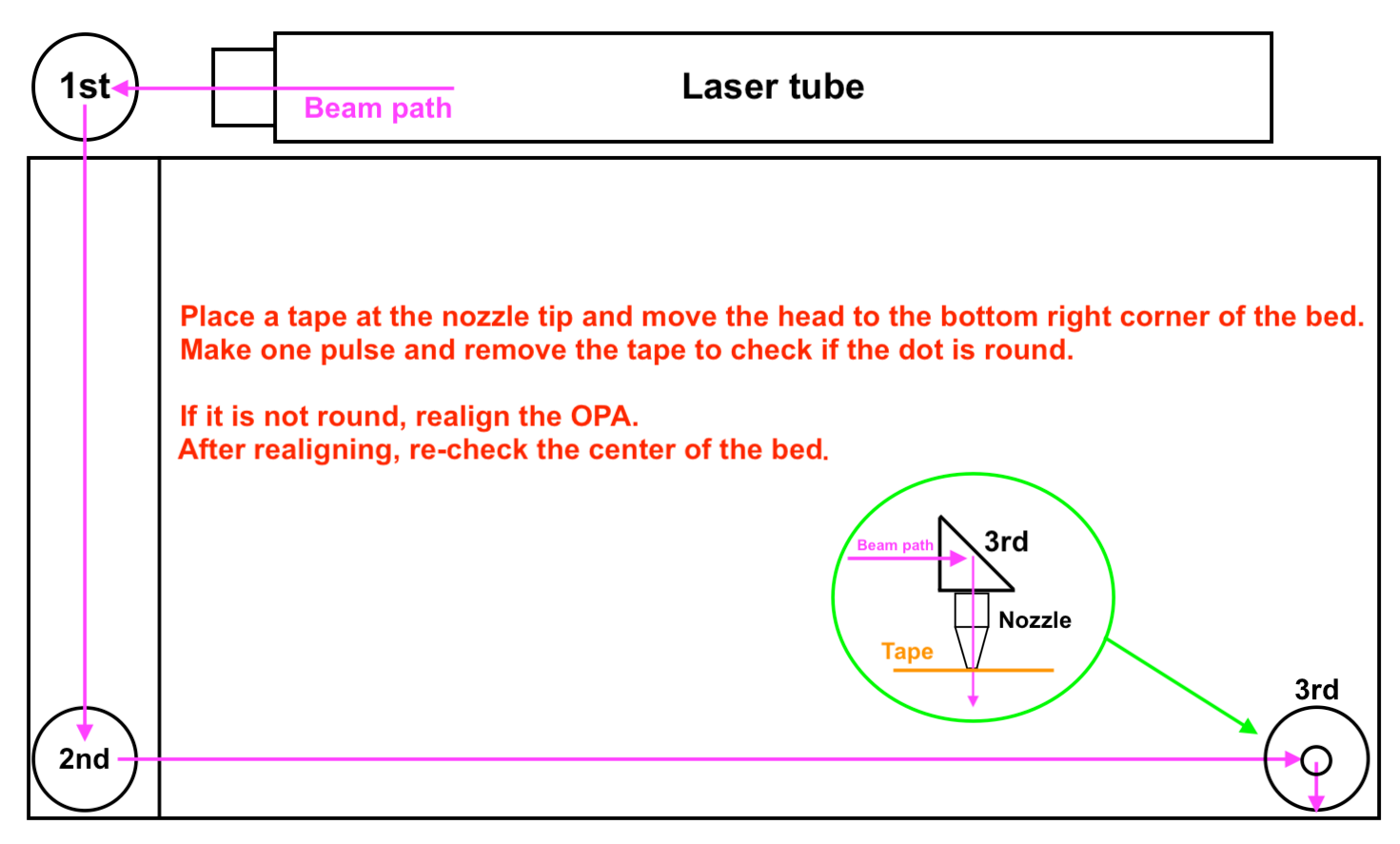
We will check the last position using tapes and pulses to see the actual CO2 laser path in the bottom-right corner of the bed.
|
Step overview - Bottom-right
|
-
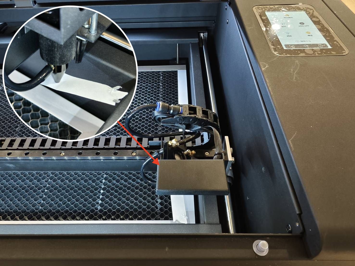
Place a one-layer tape on the nozzle tip, move the laser head to the bottom-right corner of the bed, close the door, and then make one pulse.
-
Demonstration
|
-
Remove the tape and check if the dot is round.
-
Good example - Center and Round:
-
Acceptable example - Round but a little bit off from the center:
-
Bad examples - Not Round:
|
Determine your result and the next action to take:
Step 15.1
There is still a possibility that the red laser path and the actual CO2 laser path do not match 100%.
This means that even if a red dot is adjusted perfectly, the CO2 laser path may still be off.
Therefore, we have to use the traditional way to adjust the Z-axis path.
Workflow Demonstration
-
Determine the position of the vertical dot and target the screw and its direction of rotation. First, you will have to know the whole area that the dot can move to.
It is actually the same area as the nozzle tip. The pressed mark on the tape is the area.
- Next, find the number that is similar to your vertical dot's position.
-
Schematic graph:
-
Please learn how to loosen the nut properly:
Use the pliers to hold the screw, then loosen the nut with the double-head wrench by turning it counter-clockwise.
|
For #1:
The vertical dot needs to go right in order to be round and in the center.
When facing the front of the machine:
The top-left screw will need to be rotated counter-clockwise.
Please refer to the photo below.
For #2:
The vertical dot needs to go down to the right in order to be round and in the center.
When facing the front of the machine:
The top-left screw will need to be rotated counter-clockwise in order to go right.
The bottom-right screw will need to be rotated clockwise in order to go down.
Please refer to the photo below.
For #3:
The vertical dot needs to go down in order to be round and in the center.
When facing the front of the machine:
The bottom-right screw will need to be rotated clockwise in order to go down.
Please refer to the photo below.
For #4:
The vertical dot needs to go down to the left in order to be round and in the center.
When facing the front of the machine:
The top-right screw will need to be rotated counter-clockwise.
Please refer to the photo below.
For #5:
The vertical dot needs to go left in order to be round and in the center.
When facing the front of the machine:
The top-left screw will need to be rotated clockwise.
Please refer to the photo below.
For #6:
The vertical dot needs to go up to the left in order to be round and in the center.
When facing the front of the machine:
The top-left screw will need to be rotated clockwise in order to go left.
The bottom-right screw will need to be rotated counter-clockwise in order to go up.
Please refer to the photo below.
For #7:
The vertical dot needs to go up in order to be round and in the center.
When facing the front of the machine:
The bottom-right screw will need to be rotated counter-clockwise in order to go up.
Please refer to the photo below.
For #8:
The vertical dot needs to go up to the right in order to be round and in the center.
When facing the front of the machine:
The top-right screw will need to be rotated clockwise.
Please refer to the photo below.
|
- Once you finish adjusting the screw, you have to apply a new tape and make another pulse to see the dot's position.
-
Workflow Demonstration:
- If you have difficulty using this method, you can use the red dot to know the approximate location of the actual CO2 path and then make a pulse.
-
Please tighten the nut after adjusting the screw by turning it clockwise.
|
Determine your result and the next action to take:
- The adjustment is done without a problem >> Step 14 (Recheck the Center Dot)
|
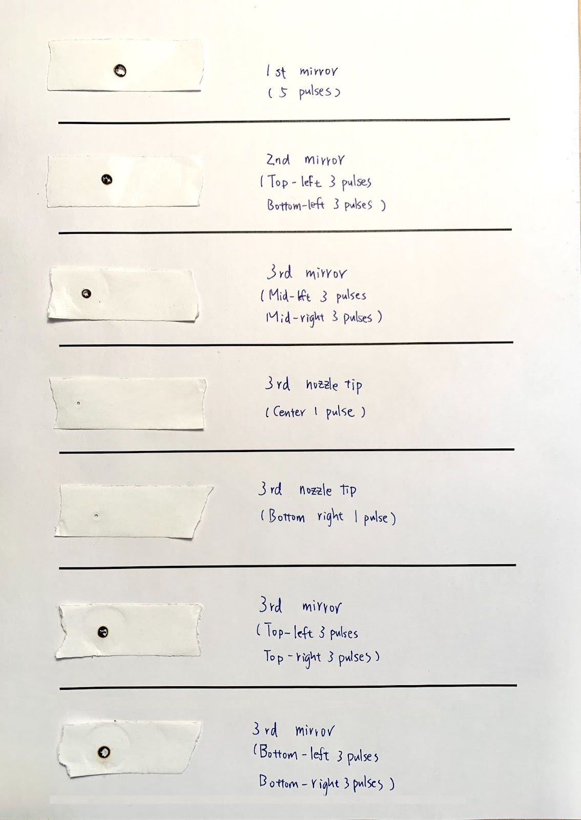
Collecting Tapes with Burnt Marks (Step 16)
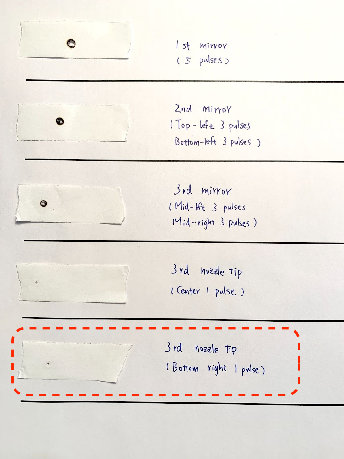
Please collect the burnt marks for the following position.
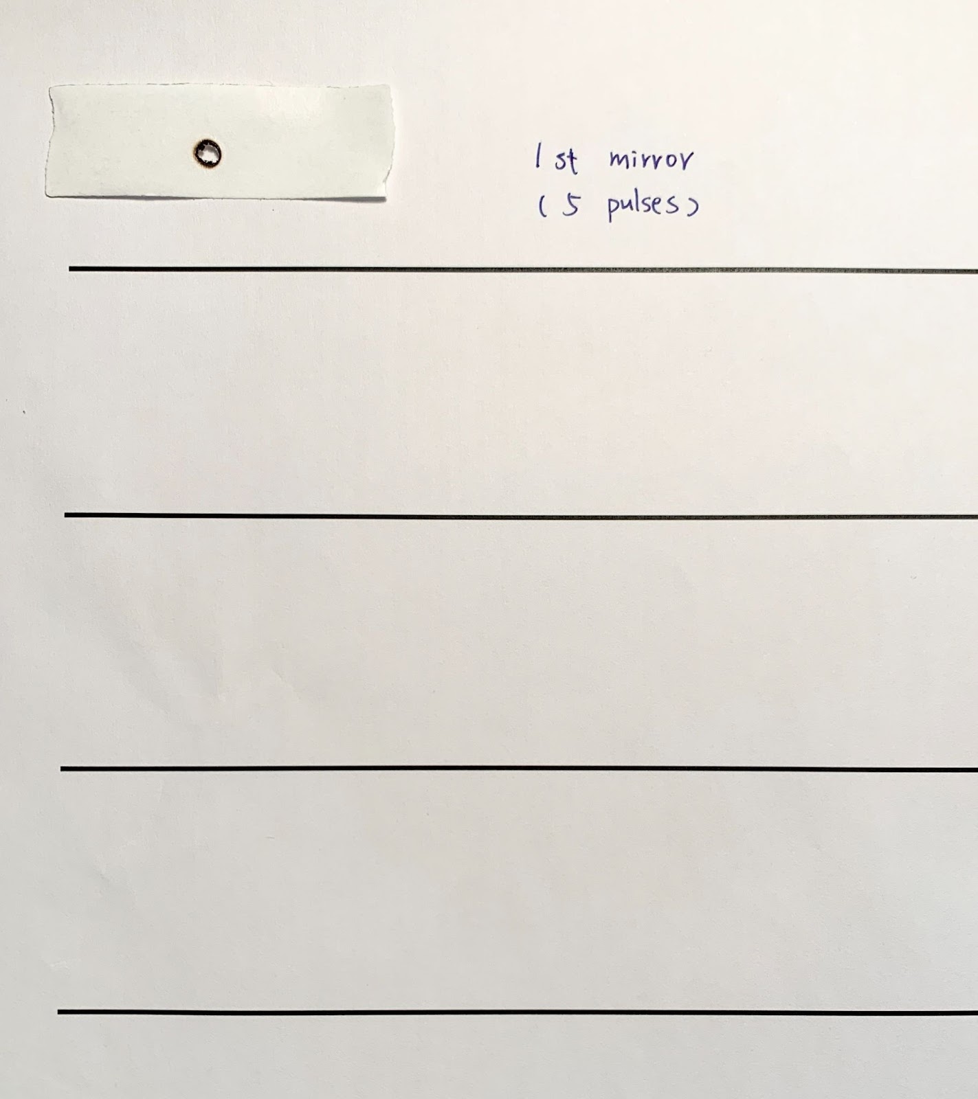
- Collect the 1st mirror mark.
Place a two-layer tape on the red light emitter to have an angle of 90 degrees against the beam and make 5 pulses.
- Paste the result on a piece of paper and write down the location.
|
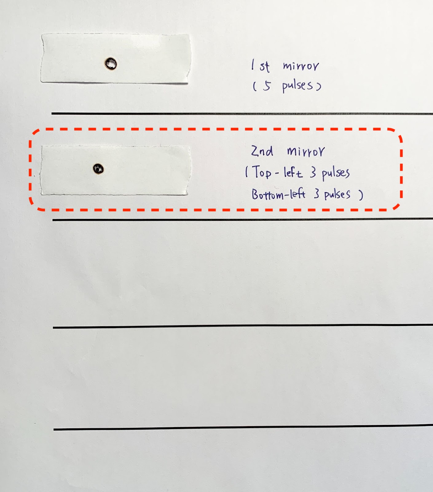
- Collect the 1st to 2nd mirror marks.
Place a two-layer tape on 2nd mirror to have an angle of 90 degrees against the beam and make 3 pulses for the top-left corner and another 3 pulses for the bottom-left corner.
- Paste the result on a piece of paper and write down the location.
|
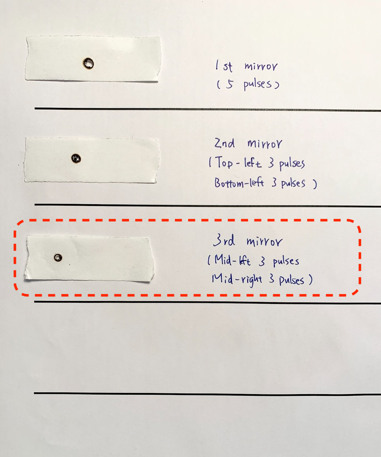
- Collect the 2nd to 3rd mirror entrance marks.
Place a two-layer tape on 3rd mirror to have an angle of 90 degrees against the beam and make 3 pulses for the middle-left side and another 3 pulses for the middle-right side.
- Paste the result on a piece of paper and write down the location.
|
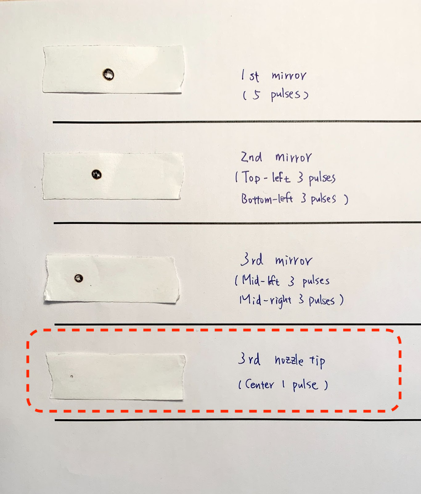
- Collect the center nozzle tip mark.
Place a one-layer tape on the nozzle tip, move the laser head to the center of the bed and make one pulse.
- Paste the result on a piece of paper and write down the location.
|
- Collect the bottom-right nozzle tip mark.
Place a one-layer tape on the nozzle tip, move the laser head to the bottom-right corner of the bed, and make one pulse.
- Paste the result on a piece of paper and write down the location.
|
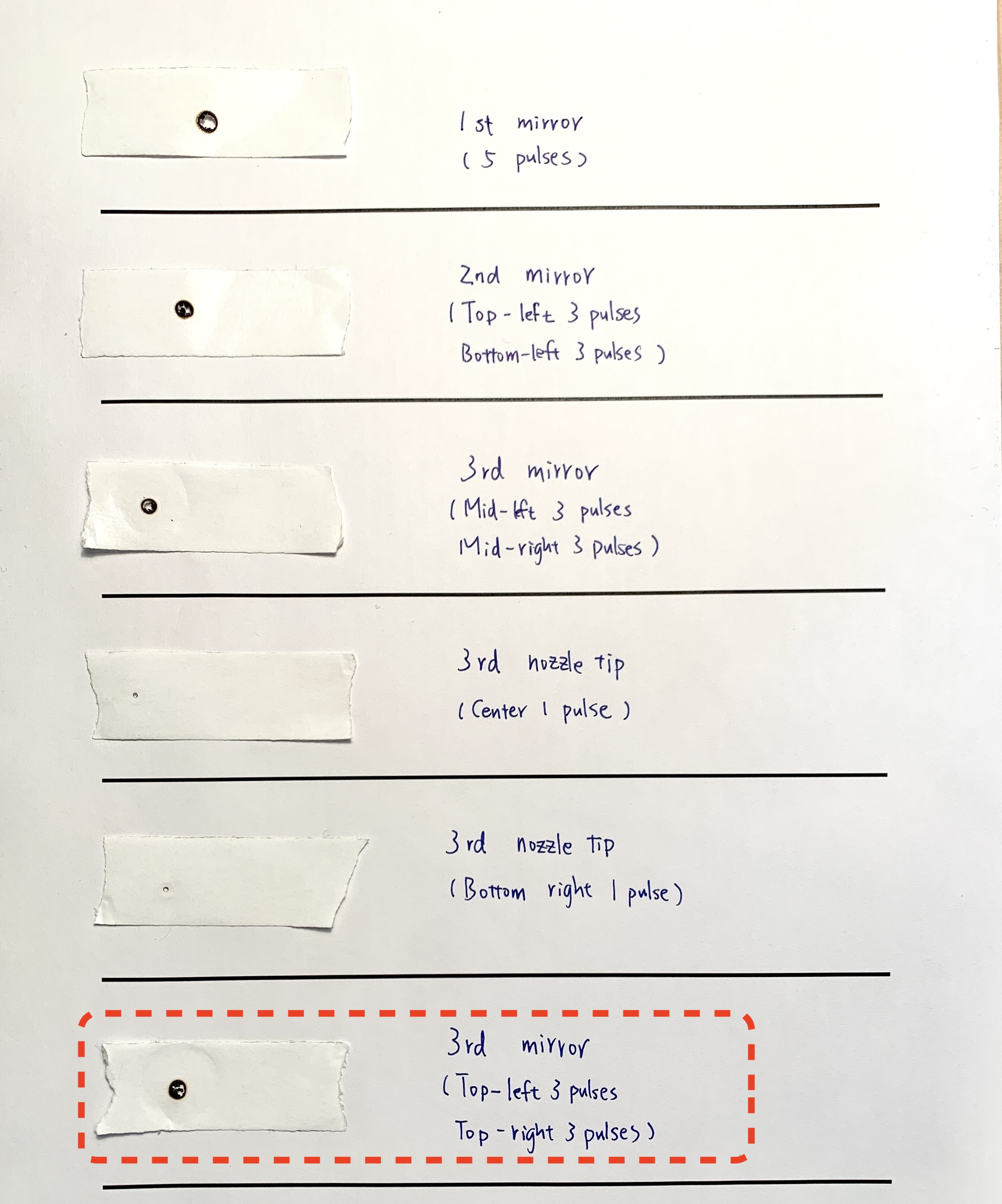
- Collect the 2nd to 3rd mirror entrance marks from top-left to top-right.
Place a two-layer tape on 3rd mirror to have an angle of 90 degrees against the beam and make 3 pulses for the top-left side and another 3 pulses for the top-right side.
- Paste the result on a piece of paper and write down the location.
|
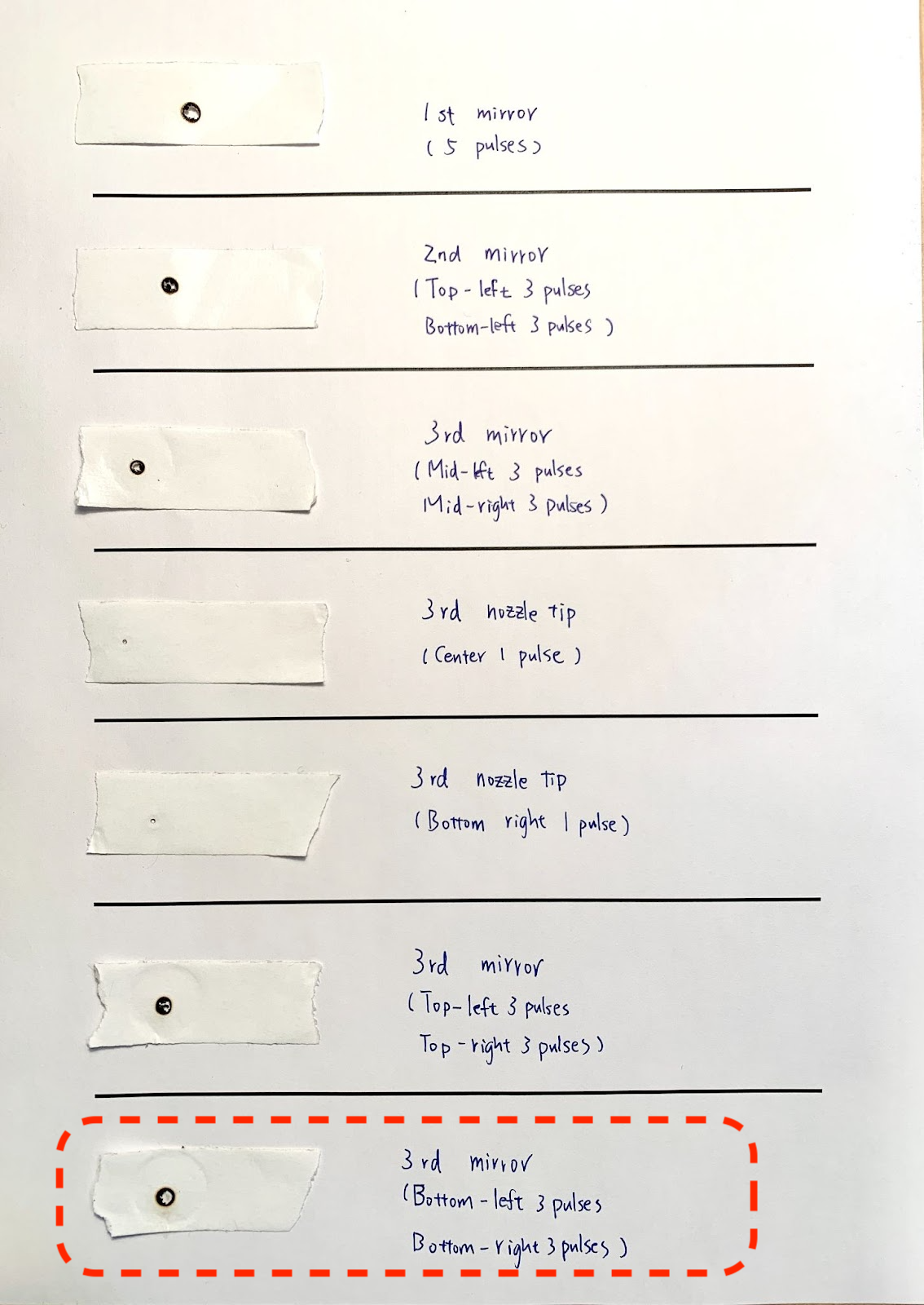
- Collect the 2nd to 3rd mirror entrance marks from bottom-left to bottom-right.
Place a two-layer tape on 3rd mirror to have an angle of 90 degrees against the beam and make 3 pulses for the bottom-left side and another 3 pulses for the bottom-right side.
- Paste the result on a piece of paper and write down the location.
|
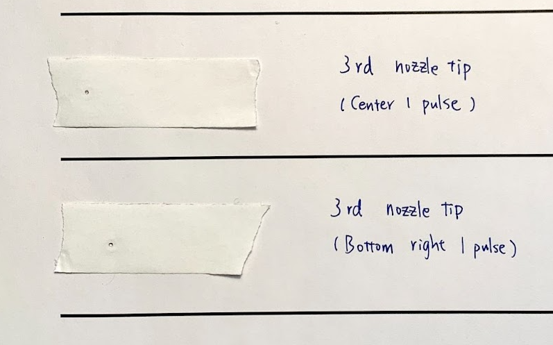
-
Finally, take a closer photo of the nozzle tip dots.
|
Reporting (Step 17)
Please contact Customer Service and send photos of your burnt marks to support.
Photo example:
#END

Comments
0 comments
Please sign in to leave a comment.